Weider 9645 Instruction Manual - Page 5
Weight Resistance Chart
 |
View all Weider 9645 manuals
Add to My Manuals
Save this manual to your list of manuals |
Page 5 highlights
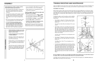
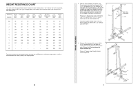
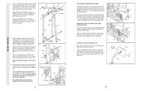
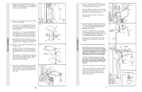
WEIGHT RESISTANCE CHART This chart shows the approximate weight resistance at each weight station. "Top" refers to the 6,5 lb. top weight. The other numbers refer to the 12,5 lb. weight plates. The butterfly arm resistance listed is the resistance for each butterfly arm. WEIGHT PLATES PRESS ARM (lbs.) BUTTERFLY ARM (lbs.) LEG LEVER (lbs.) HIGH PULLEY (lbs.) LOW PULLEY (lbs.) MILITARY PRESS ARM (lbs.) LEG PRESS (lbs.) ASSIST ARM (lbs.) Top 31 17 25 23 36 30 36 11 1 59 35 50 36 67 51 78 38 2 81 40 71 54 95 74 123 66 3 104 70 97 70 123 97 171 95 4 132 80 111 88 155 115 219 117 5 154 110 131 98 191 135 265 142 6 196 115 156 120 220 164 299 186 7 206 130 172 135 252 183 333 213 8 227 140 184 144 273 194 387 232 9 - - - - - 218 440 256 10 - - - - - 246 455 293 The actual resistance at each weight station may vary due to differences in individual weight plates, as well as friction between the cables, pulleys, and weight guides. 24 FRAME ASSEMBLY 2. Slide the Assist Upright (74) and the Leg Press Upright (56) onto the indicated 5/16" x 2 1/2" Carriage Bolts (1) in the Stabiliser (5). The high side of the brackets on the Assist Upright and Leg Press Upright should be on the side shown. Hand-tighten four 5/16" Nylon Locknuts (3) onto the Carriage Bolts. Do not tighten the Nylon Locknuts yet. Press two 2" Square Inner Caps (27) into the Leg Press Upright (56). Press a 2" Square Inner Cap into the Assist Upright (74). Attach the Rubber Bumper (91) to the Leg Press Upright (56) with the #8 x 1/2" Self-tapping Screw (87). 2 74 27 87 91 27 3 27 High Sides of Brackets 56 5 1 1 3. Slide the Front Upright (42) onto the 5/16" x 2 1/2" Carriage Bolts (1) in the Base (4). 3 Hand-tighten a 5/16" Nylon Locknut (3) onto each Carriage Bolt. Do not tighten the Nylon Locknuts yet. Press a 1" Square Inner Cap (6) into the Front Upright (42). 4 1 42 6 3 5
-
 1
1 -
 2
2 -
 3
3 -
 4
4 -
 5
5 -
 6
6 -
 7
7 -
 8
8 -
 9
9 -
 10
10 -
 11
11 -
12
-
13
-
14
-
15
-
16
-
17
-
18
-
19
 |
 |
