Weider Platinum Xp800 Canadian English Manual - Page 10
Cable 121. Attach the Pulley to a Pulley Bracket
 |
View all Weider Platinum Xp800 manuals
Add to My Manuals
Save this manual to your list of manuals |
Page 10 highlights
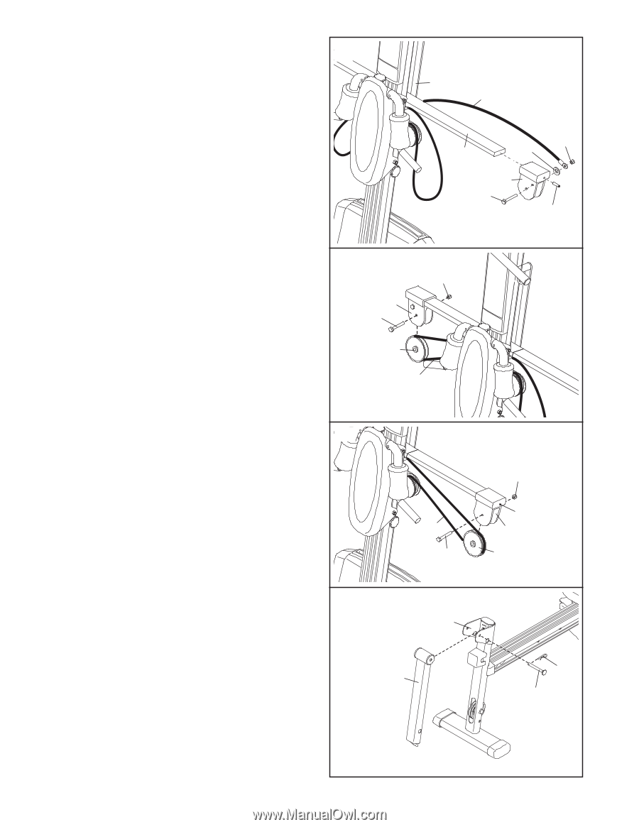
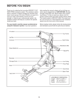
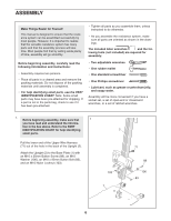
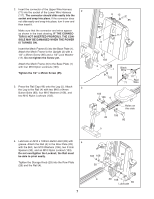
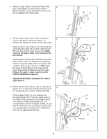
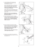
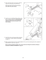
11. Insert the Resistance Bar (9) between the Crossbar Guides (15), and center it on the Crossbar Block (not shown). Press a Pulley Bracket (10) onto the Resistance Bar (9). Screw a 3/8" x 38mm Tension Screw (114) into the Pulley Bracket a couple of turns. Make sure the hexagonal hole in the Screw is on the outside of the Bracket. Attach a Tether (70) to the Pulley Bracket (10) at the upper hole with an M10 x 64mm Button Bolt (80), an M10 Thick Washer (54), and an M10 Nylon Locknut (103). Repeat on the other side of the Resistance Bar (9). Then, tighten the lower M10 x 152mm Bolt (86) used in step 10. 12. Hold a Large Pulley (14) inside of the Upper Cable (121). Attach the Pulley to a Pulley Bracket (10) with an M12 x 58mm Button Bolt (87) and an M12 Nylon Locknut (13). Make sure that the Cable is routed as shown in the CABLE DIAGRAM on page 18. 11 15 70 103 9 54 10 80 114 12 13 10 87 14 121 13. Hold a Large Pulley (14) inside of the Upper 13 Cable (121). Attach the Pulley to the other Pulley Bracket (10) with an M12 x 58mm Button Bolt (87) and an M12 Nylon Locknut (13). Make sure that the Cable is routed as shown in the CABLE DIAGRAM on page 18. Tighten the two 3/8" x 38mm Tension Screws (114) an equal number of turns. 14. Attach the Leg Lever (56) to the Leg (5) with a 14 Leg Station Pin (60). Slide a Cotter Pin (113) onto the Leg Station Pin. 121 87 13 114 10 14 5 56 113 60 10
-
 1
1 -
2
-
3
-
4
-
 5
5 -
 6
6 -
 7
7 -
 8
8 -
 9
9 -
 10
10 -
 11
11 -
 12
12 -
 13
13 -
 14
14 -
 15
15 -
16
-
17
-
18
-
19
-
20
-
21
-
22
-
23
-
24
-
25
-
26
-
27
 |
 |