Weider Precision 200 English Manual - Page 14
Cable Diagram
 |
View all Weider Precision 200 manuals
Add to My Manuals
Save this manual to your list of manuals |
Page 14 highlights
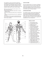
CABLE DIAGRAM The diagram below shows the proper routing of the cables. The numbers in each drawing show the proper route for that cable. Use the diagram to make sure that the cables and the cable traps are assembled correctly. If the cables are not assembled correctly, the weight system will not function properly and damage may occur. Make sure that the cable traps do not touch or bind the cables. High Cable (30) Length: 110 in. (280 cm) 4 1 2 Press Cable (29) Length: 64 in. (163 cm) 1 Low Cable (31) Length: 101 in. (256 cm) 2 3 3 5 5 4 2 1 4 3 14
-
 1
1 -
2
-
3
-
4
-
5
-
6
-
7
-
8
-
 9
9 -
 10
10 -
 11
11 -
 12
12 -
 13
13 -
 14
14 -
 15
15 -
 16
16 -
 17
17 -
 18
18 -
 19
19 -
20
 |
 |

14
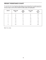
The diagram below shows the proper routing of the cables. The numbers in each drawing show the proper route
for that cable. Use the diagram to make sure that the cables and the cable traps are assembled correctly. If the
cables are not assembled correctly, the weight system will not function properly and damage may occur.
Make
sure that the cable traps do not touch or bind the cables.
1
1
1
2
2
3
4
5
2
4
4
5
3
3
High Cable (30)
Length: 110 in. (280 cm)
Press Cable (29)
Length: 64 in. (163 cm)
Low Cable (31)
Length: 101 in. (256 cm)
CABLE DIAGRAM