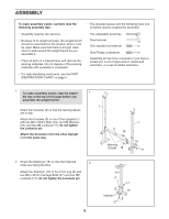
Weider Pro 256 Bench User Manual - Page 8
two M10 Washers 34, and an M10 Locknut
 |
View all Weider Pro 256 Bench manuals
Add to My Manuals
Save this manual to your list of manuals |
Page 8 highlights
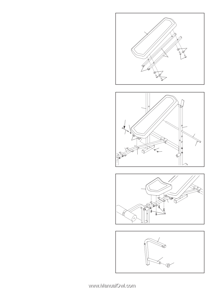
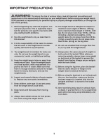
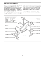
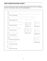
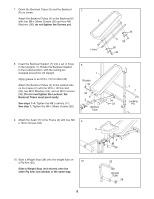
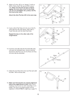
7. Orient the Backrest Tubes (5) and the Backrest (6) as shown. 7 Attach the Backrest Tubes (5) to the Backrest (6) with four M6 x 38mm Screws (30) and four M6 6 Washers (26); do not tighten the Screws yet. Holes 26 5 30 26 30 8. Insert the Backrest Support (7) into a set of holes in the Uprights (1). Rotate the Backrest Support to the locked position, with the locking pin wrapped around the left Upright. Apply grease to an M10 x 137mm Bolt (36). Attach the Backrest Tubes (5) to the welded tube on the Frame (2) with the M10 x 137mm Bolt (36), two M10 Washers (34), and an M10 Locknut (33). Do not overtighten the Locknut; the Backrest Tubes must pivot easily. See steps 1-4. Tighten the M8 Locknuts (17). See step 7. Tighten the M6 x 38mm Screws (30). 8 1 Grease 34 36 5 2 Welded Tube 9. Attach the Seat (11) to the Frame (2) with four M6 9 x 16mm Screws (29). 11 34 33 2 29 1 7 Locking Pin 10. Slide a Weight Stop (28) onto the weight tube on a Fly Arm (25). 10 Slide a Weight Stop (not shown) onto the other Fly Arm (not shown) in the same way. 25 Weight Tube 28 8
-
 1
1 -
2
-
 3
3 -
 4
4 -
 5
5 -
 6
6 -
 7
7 -
 8
8 -
 9
9 -
 10
10 -
 11
11 -
 12
12 -
 13
13 -
14
-
15
-
16
 |
 |