Weider Pro 256 Bench User Manual - Page 9
Attach the Curl Pad 45 to the Curl Post 27
 |
View all Weider Pro 256 Bench manuals
Add to My Manuals
Save this manual to your list of manuals |
Page 9 highlights
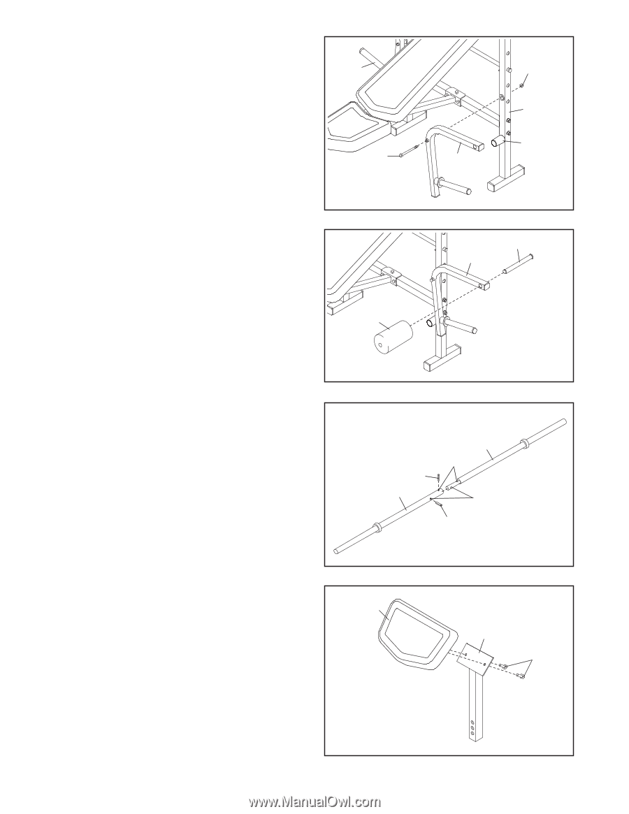
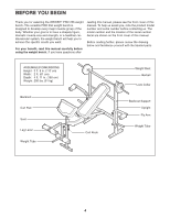
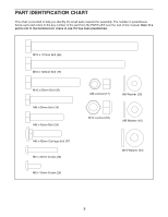
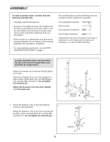
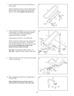
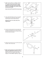
11. Attach a Fly Arm (25) to an Upright (1) with an M10 x 120mm Bolt (19) and an M10 Locknut (33). Make sure that the Fly Arm is resting against the outer side of the Fly Arm Stop (15). Do not overtighten the Locknut; the Fly Arm must pivot easily. Attach the other Fly Arm (25) in the same way. 11 25 19 33 1 15 25 12. Insert a Short Pad Tube (12) into one of the Fly Arms (25) from the side shown. Next, slide a Foam Pad (23) onto the Short Pad Tube. Repeat this step on the other side of the weight bench. 12 23 12 25 13. Insert the Inner Bar (43) into the Outer Bar (40), and align the indicated holes. Using a hammer, 13 tap the two Roll Pins (41) into the holes until they are flush with the Outer Bar. 43 Holes 41 40 Holes 41 14. Attach the Curl Pad (45) to the Curl Post (27) with two M6 x 16mm Screws (29). 14 45 15. Make sure that all parts are properly tightened before the weight bench is used. Note: Some hardware may be left over after assembly is completed. The use of all remaining parts will be explained in ADJUSTMENT, beginning on page 10. 9 27 29
-
 1
1 -
2
-
3
-
 4
4 -
 5
5 -
 6
6 -
 7
7 -
 8
8 -
 9
9 -
 10
10 -
 11
11 -
 12
12 -
 13
13 -
 14
14 -
15
-
16
 |
 |