Weider Pro 260 English Manual - Page 15
Part Identification Chart
 |
View all Weider Pro 260 manuals
Add to My Manuals
Save this manual to your list of manuals |
Page 15 highlights
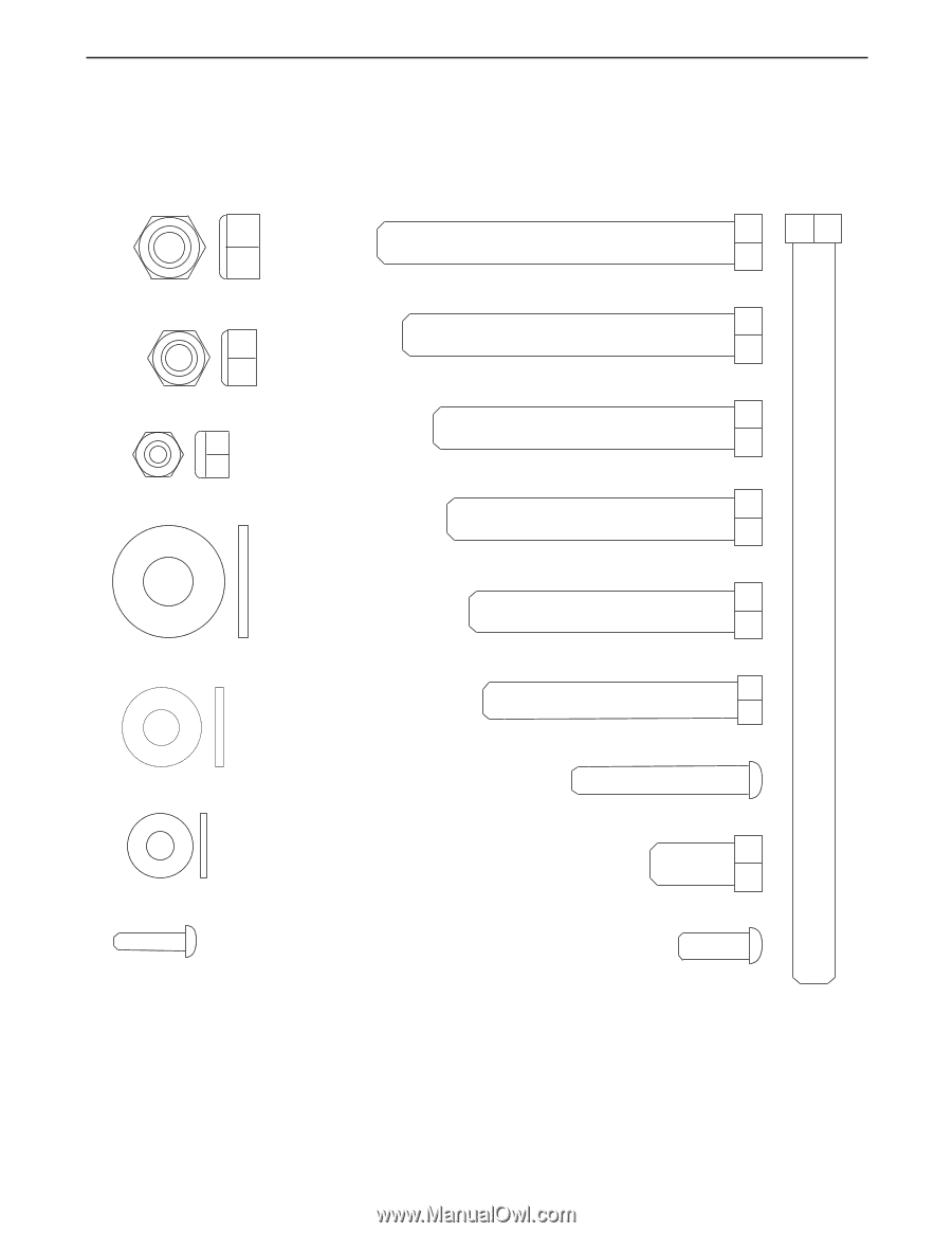
PART IDENTIFICATION CHART Refer to the drawings below to identify small parts used in assembly. The number in parentheses by each drawing is the key number of the part, from the PART LIST in the center of this manual. Note: Some small parts may have been pre-attached. If a part is not in the parts bag, check to see if it has been pre-attached. M10 x 168mm Bolt (50) M10 Nylon Locknut (43) M8 Nylon Locknut (55) M6 Nylon Locknut (51) M10 Washer (44) M8 Washer (56) M6 Washer (48) M4 x 16mm Screw (45) M10 x 81mm Bolt (41) M10 x 75mm Bolt (42) M10 x 68mm Bolt (54) M10 x 65mm Bolt (40) M10 x 60mm Bolt (47) M8 x 58mm Bolt (52) M6 x 40mm Bolt (49) M10 x 19mm Bolt (53) M6 x 16mm Screw (39)
-
 1
1 -
2
-
3
-
4
-
5
-
6
-
7
-
8
-
9
-
 10
10 -
 11
11 -
 12
12 -
 13
13 -
 14
14 -
 15
15 -
 16
16 -
 17
17 -
 18
18
 |
 |
M6 Washer (48)
M10 Nylon Locknut (43)
M10 x 168mm Bolt (50)
M4 x 16mm Screw (45)
M8 Washer (56)
M10 x 75mm Bolt (42)
M10 x 81mm Bolt (41)
M10 x 65mm Bolt (40)
M8 Nylon Locknut (55)
M8 x 58mm Bolt (52)
M6 x 16mm Screw (39)
M10 x 68mm Bolt (54)
M6 Nylon Locknut (51)
M6 x 40mm Bolt (49)
M10 x 60mm Bolt (47)
M10 x 19mm Bolt (53)
M10 Washer (44)
PART IDENTIFICATION CHART
Refer to the drawings below to identify small parts used in assembly. The number in parentheses by each draw-
ing is the key number of the part, from the PART LIST in the center of this manual.
Note: Some small parts
may have been pre-attached. If a part is not in the parts bag, check to see if it has been pre-attached.