Weider Pro 340 English Manual - Page 8
Weider Pro 340 Manual
 |
View all Weider Pro 340 manuals
Add to My Manuals
Save this manual to your list of manuals |
Page 8 highlights
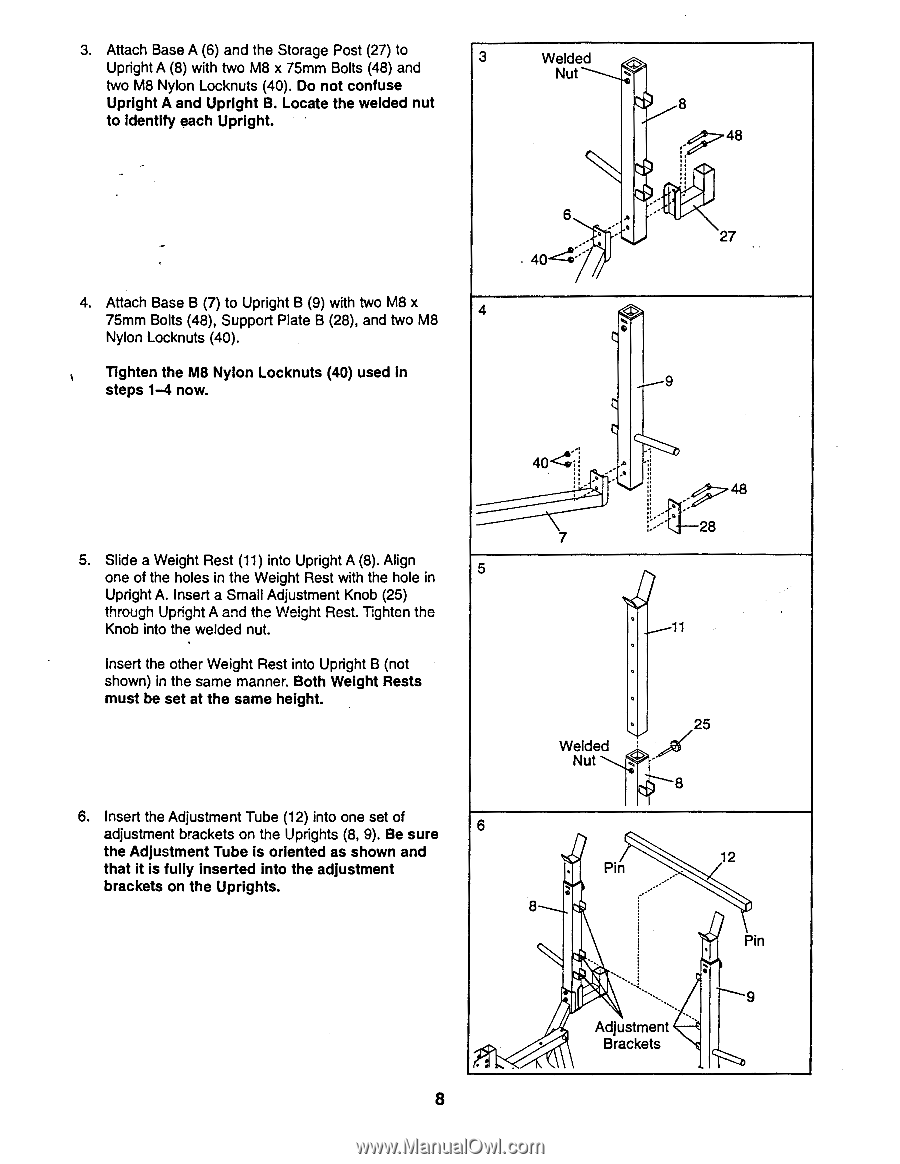
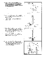
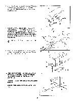
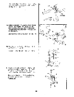
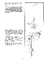
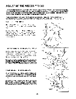
3. Attach Base A (6) and the Storage Post (27) to Upright A (8) with two M8 x 75mm Bolts (48) and 3 two M8 Nylon Locknuts (40). Do not confuse Upright A and Upright B. Locate the welded nut to Identify each Upright. • Welded Nut ...1). 8 48 4. Attach Base B (7) to Upright B (9) with two M8 x 75mm Bolts (48), Support Plate B (28), and two M8 Nylon Locknuts (40). Tighten the M8 Nylon Locknuts (40) used in steps 1-4 now. 6 -- .. ,- Aa . 40- : 4 .„. . 27 9 404 .. 48 5. Slide a Weight Rest (11) into Upright A (8). Align one of the holes in the Weight Rest with the hole in Upright A. Insert a Small Adjustment Knob (25) through Upright A and the Weight Rest. Tighten the Knob into the welded nut. Insert the other Weight Rest into Upright B (not shown) in the same manner. Both Weight Rests must be set at the same height. 6. Insert the Adjustment Tube (12) into one set of adjustment brackets on the Uprights (8, 9). Be sure the Adjustment Tube is oriented as shown and that it is fully inserted into the adjustment brackets on the Uprights. 8 7 5 i--•' 2 11 . . 25 Welded Nut .. • 8 6 12 • Pin . ...-"' 8 • . . Pin .__ . ... . 9 Adjustment Brackets
-
 1
1 -
2
-
 3
3 -
 4
4 -
 5
5 -
 6
6 -
 7
7 -
 8
8 -
 9
9 -
 10
10 -
 11
11 -
 12
12 -
 13
13 -
14
-
15
-
16
-
17
-
18
-
19
-
20
-
21
-
22
-
23
-
24
-
25
-
26
-
27
 |
 |