Weider Pro 9000 Instruction Manual - Page 6
Weight Resistance Chart
 |
View all Weider Pro 9000 manuals
Add to My Manuals
Save this manual to your list of manuals |
Page 6 highlights
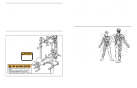
2. Slide the Centre Upright (5) onto the M10 x 2 60mm Carriage Bolts (50) in the Right and Left Bases (1, 2). Make sure that the Centre Upright is turned so the indicated bracket is on the side shown. Hand tighten two M10 Nylon Locknuts (49) onto the Bolts. Do not tighten the Nylon Locknuts yet. Bracket 5 49 49 50 1 3. Attach the Foot Plate (9) and the Rear Upright (6) 3 to the Right and Left Bases (1, 2) with two M10 x 68mm Bolts (46) and two M10 Nylon Locknuts (49). Attach the Foot Plate (9) to the Centre Upright (5) with an M10 x 68mm Bolt (46), an M10 Washer (52), and an M10 Nylon Locknut (49). Do not tighten the M10 Nylon Locknuts (49) yet. 2 6 5 1 52 49 46 46 49 9 2 6 WEIGHT RESISTANCE CHART This chart shows the approximate weight resistance at each weight station. The column labeled "WEIGHT" refers to the amount of weight, in pounds, placed on the weight carriage. The weight resistance shown for the butterfly arm station is for each butterfly arm. Note: The actual resistance at each station may vary due to friction between the cables, pulleys, and weight carriage. WEIGHT (lbs.) 10 20 30 40 50 60 70 80 90 100 110 120 130 140 150 BUTTERFLY ARM (lbs.) 9 13 17 20 24 28 31 35 38 42 46 49 53 57 61 LOW PULLEY (lbs.) 21 32 44 55 67 78 90 101 113 120 132 142 154 164 176 HIGH PULLEY (lbs.) 21 32 44 55 67 78 90 101 113 120 132 142 154 164 176 Note: 1 lb. = .454 kg 19
-
 1
1 -
 2
2 -
 3
3 -
 4
4 -
 5
5 -
 6
6 -
 7
7 -
 8
8 -
 9
9 -
 10
10 -
 11
11 -
 12
12 -
13
-
14
 |
 |
