Weslo Body Shop 2 English Manual - Page 6
Assembly
 |
View all Weslo Body Shop 2 manuals
Add to My Manuals
Save this manual to your list of manuals |
Page 6 highlights
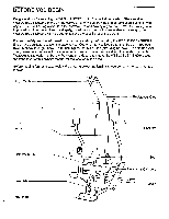
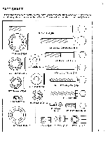
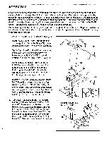
ASSEMBLY Place all parts of the cross training system in a cleared area. Due to the weight of the cross training system, it should be assembled in the location where it will be used. Remove all packing materials, except for the ties securing the Cable (73) (see assembly step 5). Do not dispose of the packing materials until assembly is completed. Assembly requires two persons. Read each step and examine each drawing carefully. Make sure that all parts are oriented as shown in the drawings. Refer to the PART CHART on page 5 for help identifying the small parts used in assembly. The following tools (not Included) are required: two adjustable wrenches, a phillips screwdriver, a set of alien wrenches and a rubber mallet. A small amount of grease and a small bowl of soapy water are also needed. 1. Press two 2" x 3" Caps (33) into the Base (71). Insert the six 3/8" x 2 1/2" Carriage Bolts (8) up through the holes in the Base (71). Finger tighten six 3/8" Bolts (1) onto the Carriage Bolts. 1 93 44 90 57 68 93 Tip the Upright (67) and look into the opening in the lower end (see the inset drawing). Make sure that the Cable (73) is routed around the indicated Thin 3 1/2" Pulley (35). 44 Remove the 3/8" Nuts (1) from the 3/8" x 2 1/2" Carriage Bolts (8) in the Base (71). Slide the Upright (67) onto the Carriage Bolts. Tighten the six 3/8" Nuts onto the Carriage Bolts. Make sure that the hearic of the Carriage Bolts are against the Base. Insert the 7/8" x 16" Handle (57) into the Handlebar Tube (68) and center it. Using an alien wrench, tighten the 1/4" Set Screw (90) into the Handlebar Tube. Wet the ends of the Handle with soapy water. Slide a Foam Grip (44) onto each end of the Handle. Press a 7/8" Round Cap (93) into each end of the Handle. 2. Tap a 1/2" Retainer (26) and 1/2" Retainer Cap (29) onto one end of the 1/2" x 6 1/2" Axle (46). Make sure that the teeth on the Retainer bend toward the Retainer Cap. Align the lower end of the Moment Arm (72) with the indicated brackets on the Base (71). Insert the Axle through the Moment Arm and the Base. Tap a 1/2" Retainer (26) and 1/2" Retainer Cap (29) onto the other end of the Axle. 67 33 71 33 8 8 2 Selector Knob must be on this side 72 29?' 26 67 73 35 71 6 46 26 O-29
-
 1
1 -
 2
2 -
 3
3 -
 4
4 -
 5
5 -
 6
6 -
 7
7 -
 8
8 -
 9
9 -
 10
10 -
 11
11 -
 12
12 -
13
-
14
-
15
-
16
-
17
-
18
 |
 |
