Weslo Body Shop 2 English Manual - Page 7
around
 |
View all Weslo Body Shop 2 manuals
Add to My Manuals
Save this manual to your list of manuals |
Page 7 highlights
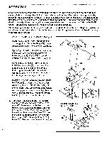
3. Press 1 1/2" Round Caps (31) into the upper and lower ends of the Left and Right Arms (54, 55). Wet the upper ends of the Left and Right Arms (54, 55) with soapy water. Slide the Large Pads (43) onto the Arms. Tap the four 3/4" Bushings (20) into the Moment Arm (72). Insert the pin on the lower end of the Right Arm (55) through two of the Bushings (20) in the Moment Arm (72). Make sure that the lower end of the Right Arm is between the Selector Plate (47) and the Indicated tab on the Moment Arm (see the Inset drawing). Tap a 3/4" Retainer (25) and 3/4u Retainer Cap (28) onto the pin. Make sure that the teeth on the Retainer bend toward the Retainer Cap. Attach the Left Arm (54) to the Moment Arm (72) in the same manner. 3 [3- 43 55 Pin 20 /1'0 20-4 72 25-+ 28- cql Tab; 47 41 it I , 43 54 4. Attach a Thick 3 1/2" Pulley (34) to the Right 4 Arm (55) with a 3/8" x 2 1/4" Bolt (12), Cable Trap (37) and 3/8" Nylock Nut (1). Do not tighten the Nylock Nut yet. Attach a Thick 3 1/2" Pulley (34) to the Left 54 Arm (54) in the same manner. 37 34 55 0 5. Remove the ties securing the Cable (73). Hold the Cable to keep tension on it until assembly step 6 Is completed. Route the Cable around the Thick 3 1/2" Pulley (34) on the Right Arm (55). Route the Cable around the Thick 3 1/2" Pulley on the Left Arm (54). Make sure that the Cable is between the Pulleys and the Cable Traps (37). Tighten the Nylock Nuts (1) shown in assembly step 4. Make sure that the Pulleys turn freely. Route the Cable (73) down through the "U" Bracket (62) (see the inset drawing). Attach a Thick 31/2" Pulley (34) to the "U" Bracket with a 3/8" x 2 1/4' Bolt (12) and 3/8" Nylock Nut (1). 5 34 54 37 55 34 r 34 73 o 7162 1
-
 1
1 -
 2
2 -
 3
3 -
 4
4 -
 5
5 -
 6
6 -
 7
7 -
 8
8 -
 9
9 -
 10
10 -
 11
11 -
 12
12 -
13
-
14
-
15
-
16
-
17
-
18
 |
 |
