Weslo Cadence 975 English Manual - Page 5
completed.
 |
View all Weslo Cadence 975 manuals
Add to My Manuals
Save this manual to your list of manuals |
Page 5 highlights
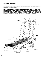
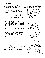
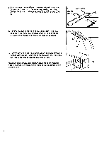
ASSEMBLY Assembly requires two people. Set the treadmill in a cleared area and remove all packing materials. Do not dispose of the packing materials until assembly is completed. THE FOLLOWING TOOLS ARE REQUIRED FOR ASSEMBLY: The included 7/32" alien wrench and your own adjustable wrench f==:sef) . 1. Locate the Right Upright (15), which has a large hole near the upper end (see the inset drawing). Insert a 3/8" x 31/2" Bolt (23), with a Flat Washer (7), into the hole in the lower end of the Right Upright. Finger tighten the Bolt into the indicated hole in the Frame (47). Insert a 3/8" x 3 " Bolt (97), with a Flat Washer (7), into the lower end of the handrail on the Right Upright (15). Finger tighten the Bolt into the indicated hole in the Frame (47). Attach the Left Upright (not shown) in the same manner. 47 15 15 15 7 97 7 23 2. Hold the Console (12) near the Right Upright (15). Feed the 70" Wire Harness (10) into the large hole, until the end comes out the bottom of the Right Upright. If necessary, insert your fingers into the bottom of the Right Upright and pull out the end of the 70" Wire Harness. Insert the Cable Loom (11) into the large hole in the Right Upright. Using the 7/32" Allen Wrench (1) and an adjustable wrench, attach the Console Plate (6) to the Right Handrail (15) with two 3/8" x 2" Bolts (2), Flat Washers (7) and 3/8" Jam Nuts (8). 2 6 11 12 8 7 2 15 10 3. Using the 7/32" Allen Wrench (1) and an adjustable wrench, attach the Console Plate (11) to the Left Handrail (3) with two 3/8" x 2" Bolts (2), Flat Washers (7) and 3/8" Jam Nuts (8). 3 11 2 Tighten the four Bolts (23, 97) used in assembly step 1 (see 8 assembly step 1). 7 3 4. Plug the lower end of the 70" Wire Harness (11) into the 20" Wire Harness (28). The small latch on the 70" Wire Harness should snap onto the 20" Wire Harness (see the upper inset drawing). If the Wire Harnesses do not fit easily, turn them; do not force the Wire Harnesses together. Adjust the 12" Cable Loom (27) so that it is inserted into the Right Upright (15) and the Safety Cover (50) (see the lower inset drawing). Be careful not to damage the Wire Harnesses. 28 11 15 50 27 5
-
 1
1 -
 2
2 -
 3
3 -
 4
4 -
 5
5 -
 6
6 -
 7
7 -
 8
8 -
 9
9 -
 10
10 -
 11
11 -
12
-
13
-
14
-
15
-
16
 |
 |
