Weslo Cardioglide 950 English Manual - Page 3
shown
 |
View all Weslo Cardioglide 950 manuals
Add to My Manuals
Save this manual to your list of manuals |
Page 3 highlights
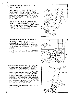
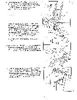
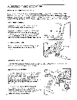
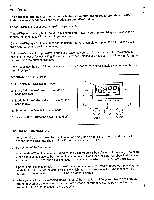
1. Tap a 1/2" Bushing (25) into each side of the Frame (6) as shown. Apply grease to the 1/2" x 11 1/2" Pivot Rod (21). Align the holes in the Pedal Frame (7) with the indicated tube on the Frame (6). Tap the Pivot Rod through the Pedal Frame and the Frame. Center the Pivot Rod and tap a 1/2" Dome Cap (29) onto each end of it. Make sure that the Magnet (27) is on the Pedal Frame (7) and that it is properly adjusted (see ADJUSTING THE MAGNET AND REED SWITCH on page 8). If the Magnet is not aligned with the reed switch, the monitor will not function. Apply Grease 29 21 7 6 25 111 0 0 II II 29 27 2. Make sure that there is a 1/2" Link Arm Bushing (19) in the right Link Arm (4) (see the inset drawing). Slide the right Link Arm onto the indicated pin on the Pedal Frame (7). Pivot the Pedal Frame and tap a 1/2" Dome Cap (29) onto the pin. Attach the left Link Arm (not shown) in the same manner. 4 19 7 29 4 Pin 19 3. Make sure that there is a 1 1/4" x 2" Endcap (13) on each end of the Handlebar (2). The Endcaps must be turned so the round holes are on top. Slide the Handlebar (2) into the Pedal Frame (7). The Handlebar must be turned so the indicated holes are facing away from the seat. Align the holes in the Handlebar with the holes in the Pedal Frame. Attach one side of the Handlebar with two #8 x 1/2" Screws (16). Attach the other side of the Handlebar with two #8 x 1/2" Screws. Slide the 1 1/4" x 2" Endcaps (13) down over the Pedal Frame (7). 4 2 13 Holes 7 16
-
 1
1 -
 2
2 -
 3
3 -
 4
4 -
 5
5 -
 6
6 -
 7
7 -
 8
8 -
 9
9 -
10
-
11
 |
 |
