Weslo Cardioglide 950 English Manual - Page 4
rounded
 |
View all Weslo Cardioglide 950 manuals
Add to My Manuals
Save this manual to your list of manuals |
Page 4 highlights
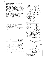
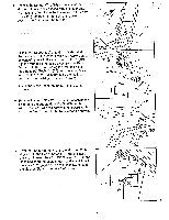
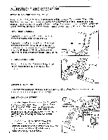
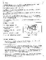
Connect the Sensor Wire (15) to the wire on the - Monitor (1). Insert any excess wire into the Frame (6). Attach the Monitor to the Frame with a #8 x 1/2" Screw (16). Make sure not to pinch the wire between the Frame and the Monitor. 1 0.,2,0.. 15 .. i 16 / / _ 6 5. Slide a 3/8" Spacer (20) onto the indicated shaft on the lower end of the Pedal Frame (7). Apply a small amount of grease to the shaft. Slide a Pedal (12), with the rounded end facing away from the Pedal Frame, onto the shaft. Using the included pedal tool, tap a 1/2" Push Nut (30) onto the shaft. Make sure that the Push Nut is turned so the teeth bend away from the Pedal (see the inset drawing). Attach the other Pedal (not shown) in the same manner. 6. Remove the two 1/4" x 2" Screws (17) attaching the Seat (3) to the underside of the Seat Tube (5). Attach the Seat, with the narrow end forward, to the top of the Seat Tube with the two Screws as shown. 7 Apply Grease , < ._ 20 12 7 1 Teeth s, 30 Pedal 30 Tool Narrow End 3 ■ i 5 17 7. Pivot the Pedal Frame (7) until the Magnet (27) is aligned with the Reed Switch (15) (see the inset drawing). Loosen the #8 x 3/4" Screw (35). Turn the Reed Switch to the angle shown, and adjust it until there is a 1/8" gap between the Reed Switch and - the Magnet. Tighten the #8 x 3/4" Screw. 7 \
-
 1
1 -
 2
2 -
 3
3 -
 4
4 -
 5
5 -
 6
6 -
 7
7 -
 8
8 -
 9
9 -
 10
10 -
11
 |
 |
