Weslo Flex 505 English Manual - Page 7
Adjustment
 |
View all Weslo Flex 505 manuals
Add to My Manuals
Save this manual to your list of manuals |
Page 7 highlights
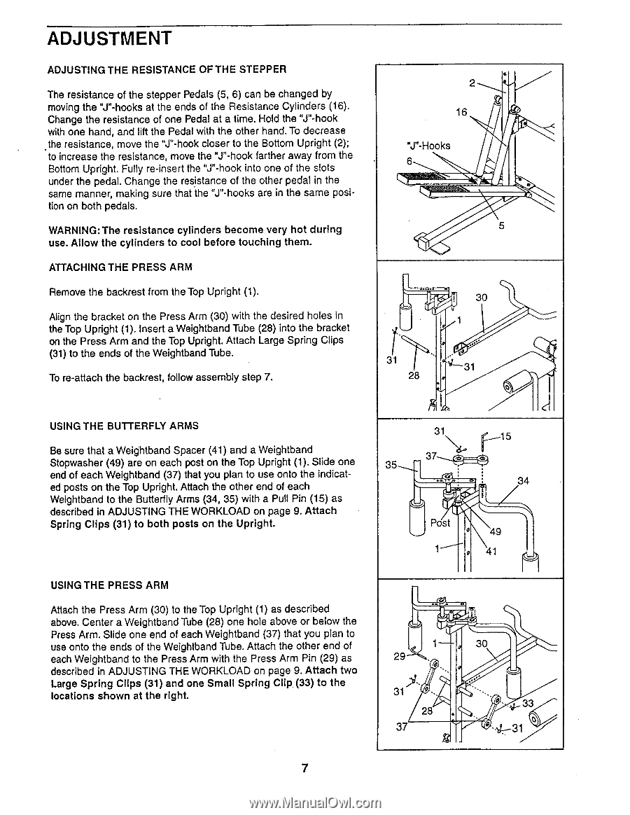
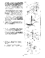
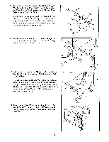
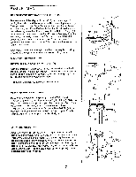
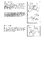
ADJUSTMENT ADJUSTING THE RESISTANCE OF THE STEPPER The resistance of the stepper Pedals (5, 6) can be changed by moving the "J"-hooks at the ends of the Resistance Cylinders (16). Change the resistance of one Pedal at a time. Hold the "J"-hook with one hand, and lift the Pedal with the other hand. To decrease the resistance, move the "J"-hook closer to the Bottom Upright (2); to increase the resistance, move the "J"-hook farther away from the Bottom Upright. Fully re-insert the "J"-hook into one of the slots under the pedal. Change the resistance of the other pedal in the same manner, making sure that the "J"-hooks are in the same position on both pedals. WARNING:The resistance cylinders become very hot during use. Allow the cylinders to cool before touching them. ATTACHING THE PRESS ARM Remove the backrest from the Top Upright (1). Align the bracket on the Press Arm (30) with the desired holes in the Top Upright (1). Insert a Weightband Tube (28) into the bracket on the Press Arm and the Top Upright. Attach Large Spring Clips (31) to the ends of the Weightband Tube. To re-attach the backrest, follow assembly step 7. USING THE BUTTERFLY ARMS Be sure that a Weightband Spacer (41) and a Weightband Stopwasher (49) are on each post on the Top Upright (1). Slide one end of each Weightband (37) that you plan to use onto the indicated posts on the Top Upright. Attach the other end of each Weightband to the Butterfly Arms (34, 35) with a Pull Pin (15) as described in ADJUSTING THE WORKLOAD on page 9. Attach Spring Clips (31) to both posts on the Upright. USING THE PRESS ARM Attach the Press Arm (30) to the Top Upright (1) as described above. Center a Weightband Tube (28) one hole above or below the Press Arm. Slide one end of each Weightband (37) that you plan to use onto the ends of the Weightband Tube. Attach the other end of each Weightband to the Press Arm with the Press Arm Pin (29) as described in ADJUSTING THE WORKLOAD on page 9. Attach two Large Spring Clips (31) and one Small Spring Clip (33) to the locations shown at the right. 2 • 16 "J"-Hooks 6 i i 5 30 1 31 x- 31 28 o kh 31 f_..-15 37 . 35 34 Post ° 49 1 ® 41 1 „ 30 29---1'0 ,14 ..' 31 ° • 4 28 . ♦. • ° • 4...33 o 37 ° -4-31 7
-
 1
1 -
 2
2 -
 3
3 -
 4
4 -
 5
5 -
 6
6 -
 7
7 -
 8
8 -
 9
9 -
 10
10 -
 11
11 -
 12
12
 |
 |