Weslo Momentum 950 Elliptical User Manual - Page 6
short tube on the Left Upper Body Arm. Slide the Left
 |
View all Weslo Momentum 950 Elliptical manuals
Add to My Manuals
Save this manual to your list of manuals |
Page 6 highlights
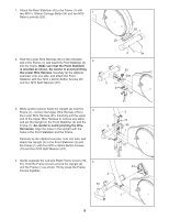
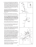
5. Hold the Console Bracket (26) near the Upright (2), and locate the wire extending from the bottom of the Console Bracket. Carefully pull the upper end of the Upper Wire Harness (79) to remove any slack, and tie the wire around the Upper Wire Harness, as shown in the inset drawing. Carefully pull the wire up through the Console Bracket until the Upper Wire Harness is extending from the top of the Console Bracket. Then, untie the wire and discard it. Insert the Console Bracket (26) into the Upright (2). Be careful to avoid pinching the Upper Wire Harness (79). Attach the Console Bracket with three M8 x 25mm Button Screws (57) and three M8 Split Washers (74). 6. Identify the Left Upper Body Arm (9) and the Left Upper Body Leg (73), which are marked with stickers. Insert the Left Upper Body Arm (9) into the Left Upper Body Leg (73). Make sure that the short tube on the Left Upper Body Arm and the hexagonal holes in the Left Upper Body Leg are on the same side. Attach the Left Upper Body Arm with two M8 x 42mm Button Bolts (50) and two M8 Nylon Locknuts (46). Do not tighten the Button Bolts yet. Attach the Right Upper Body Arm (not shown) to the Right Upper Body Leg (not shown) in the same way. 7. Insert the Pivot Axle (38) into the Upright (2), and center the Pivot Axle. Apply a generous amount of the included grease to the Pivot Axle. Identify the Left Upper Body Arm (9), which is marked with a sticker. Slide a Handlebar Spacer (25) onto the short tube on the Left Upper Body Arm. Slide the Left Upper Body Arm onto the Pivot Axle (38). Orient a Handlebar Cap (23) as shown, and slide it onto the lower end of the Left Handlebar (87). Slide the upper end of the Left Handlebar (87) into the tube on the front of the Console Bracket (26), while sliding the lower end of the Left Handlebar onto the Pivot Axle (38). Attach the upper end of the Left Handlebar with two M8 x 41mm Button Bolts (91) and two M8 Jam Nuts (93); make sure the Jam Nuts are resting in the hexagonal holes in the Console Bracket. Attach the lower end of the Left Handlebar with an M8 x 35mm Button Bolt (90) and an M8 Jam Nut (93). Then, press the tabs on the Handlebar Cap (23) into the Handlebar Spacer (25). Assemble the Right Upper Body Arm (10) and the Right Handlebar (88) in the same way. Gently separate the two Upright Covers (82). Hold the Upright Covers around the Upright (2), and firmly press the Upright Covers together. 6 5 Wire 26 79 57 74 6 79 2 74 57 9 50 73 Tube 46 Hexagonal Holes 7 87 10 88 93 91 26 9 82 38 23 82 25 90 Tube Grease 93 Tab 2
-
 1
1 -
 2
2 -
 3
3 -
 4
4 -
 5
5 -
 6
6 -
 7
7 -
 8
8 -
 9
9 -
 10
10 -
 11
11 -
 12
12 -
13
-
14
-
15
-
16
-
17
-
18
-
19
-
20
 |
 |
