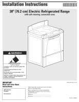
Whirlpool GR556LRKS Installation Instructions - Page 5
Direct wire method
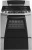 |
View all Whirlpool GR556LRKS manuals
Add to My Manuals
Save this manual to your list of manuals |
Page 5 highlights
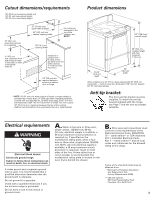
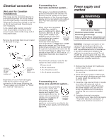
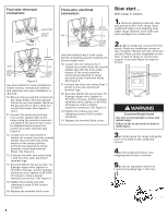
Four-wire electrical connection: Use this method for new installations, mobile homes, recreational vehicles, and whenever four-wire installation is required. 7. Remove the ground-link screw from the range frame. Save the groundlink screw. Bend up the ground link so that it does not contact the range. Three-wire electrical connection: silver-colored terminal block screw ground link line 2 neutral (center wire) ground link ground-link screw 8. Connect the green ground wire from power supply cord to the range using the ground-link screw. The ground wire must be attached first and must not contact any other terminal. groundlink screw green ground wire 9. Connect the neutral (center wire) wire to the center, silver-colored terminal screw on the terminal block using the brass nuts that are attached to the terminal block cover. silver-colored terminal block screw line 1 U.L.-listed strain relief and 40 amp range power supply cord Use this method only if local codes permit connecting cabinet-ground conductor to neutral wire of power supply cord. 7. Use the brass terminal nuts attached to the terminal block cover to connect the neutral wire (center wire) to the silver-colored terminal screw on the terminal block. 8. Connect the other two wires to outer terminal screws on the terminal block. 9. Do not loosen factory-installed nuts already on the terminal. Tighten nuts with 3/8" nut driver for proper electrical connection. 10. Tighten the strain relief screws. 11. Reinstall the terminal block cover. Direct wire method NOTE: The bag containing three aluminum terminal lugs must be used when making a direct wire connection. supply cable. Depending on your electrical supply, make the required three-wire or four-wire connection. 1. Disconnect power. 2. Remove the knockout for the power supply cable. 3. Assemble a U.L.-listed conduit connector in the opening. U.L.-listed conduit connector 4. Strip the insulation back 1 inch from the end of each wire. 1" 5. Allow enough slack in the wire to easily attach the wiring to the terminal block. 6. Use 3/8" nut driver and remove the outside nuts on the terminal block screws. Do not loosen the factorytightened nuts behind the outside nuts. 7. IMPORTANT: the aluminum lugs must be assembled to the terminal posts with the set screws facing out as shown. aluminum lug terminal screw set screw must face out green ground wire neutral wire (center wire) U.L. listed strain relief and 40 amp range power supply cord 10. Connect the other two wires to the outer terminals on the terminal block. 11. Do not loosen the factory installed nuts already on the terminal. Tighten nuts with 3/8" nut driver for proper electrical connection. 12. Tighten the strain relief screws. 13. Replace the terminal block cover. WARNING Electrical Shock Hazard Disconnect power before servicing. Use 8 gauge copper wire, or 6 gauge aluminum wire. Electrically ground range. Failure to follow these instructions can result in death, fire, or electrical shock. 8. Attach three aluminum lugs to terminal posts. Use a 3/8" nut driver and tighten the nuts securely. Nuts must be tightened to 20 in/lbs of torque for proper electrical connection. 9. Complete electrical connection according to your type electrical supply ("Four-wire electrical connection" or "Three-wire electrical connection.") This range may be connected directly to the fuse disconnect or circuit breaker box; or with a U.L.-listed, 40 amp range power 5
-
 1
1 -
 2
2 -
 3
3 -
 4
4 -
 5
5 -
 6
6 -
 7
7 -
 8
8 -
 9
9 -
 10
10 -
 11
11 -
12
-
13
-
14
-
15
-
16
 |
 |
