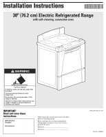
Whirlpool GR556LRKS Installation Instructions - Page 6
Installation steps - washers
 |
View all Whirlpool GR556LRKS manuals
Add to My Manuals
Save this manual to your list of manuals |
Page 6 highlights
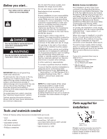
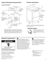
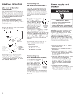
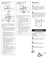
Four-wire electrical connection: ground link ground screw Figure 1 slotted set screw line 1 line 2 green ground wire neutral (center wire) Figure 2 Use this method for new installations, mobile homes, recreational vehicles, and whenever four-wire installation is required. 10. Remove the ground-link screw from the range frame. Save the groundlink screw and cup washer. Bend up the ground link so that it does not contact the range. See Figures 1 and 2. 11. Connect the green ground wire from power supply cable to the range using the ground screw and cup washer. The ground wire must be attached first and must not contact any other terminal. See Figure 2. 12. Loosen (do not remove) the 3 slotted set screws. Insert the neutral (white) wire into the hole at the bottom of the center position terminal lug (attached to center terminal screw black terminal block). See Figure 2. 13. Connect the other two wires (lines 1 and 2) to the outer aluminum terminal lugs. 14. Securely tighten the set screws. For 8 gauge copper wire, tighten to 25 in/lbs of torque, and for 6 gauge aluminum wire, tighten to 35 in/lbs of torque to make a proper electrical connection. See Figure 2. 15. Tighten the locking ring and clamping screws of the conduit connector. 16. Replace the terminal block cover. Three-wire electrical connection: slotted set screw line 1 Figure 3 line 2 neutral (center wire) Use this method only if local codes permit connecting ground conductor to neutral supply wire. 10. Loosen (do not remove) the 3 slotted set screws. Insert the neutral (white) wire into the hole at the bottom of the center position terminal lug (attached to center terminal screw of terminal block). See Figure 3. 11. Connect the other two wires (lines 1 and 2) to the outer aluminum terminal lugs. 12. Securely tighten the set screws. For 8 gauge copper wire, tighten to 25 in/lbs of torque, and for 6 gauge aluminum wire, tighten to 35 in/lbs of torque to make a proper electrical connection. See Figure 3. 13. Tighten the locking ring and clamping screws of the conduit connector. 14. Replace the terminal block cover. Now start... With range in kitchen. 1. Remove shipping materials, tape and protective film from range. Keep cardboard bottom and shipping base under range. Remove oven racks and parts package from inside oven. 2. Take 4 cardboard corners from the carton. Stack one cardboard corner on top of another. Repeat with the other two corners. Place corners lengthwise on the floor in back of range so corners will support outer side edges of range as shown. cardboard corners spacers WARNING Excessive Weight Hazard Use two or more people to move and install range. Failure to do so can result in back or other injury. 3. Firmly grasp the range and gently lay it on its back on the cardboard corners. 4. Pull cardboard bottom and shipping base firmly to remove. 5. Use an adjustable wrench to loosen the leveling legs 1-1/2 turns. 6
-
 1
1 -
 2
2 -
 3
3 -
 4
4 -
 5
5 -
 6
6 -
 7
7 -
 8
8 -
 9
9 -
 10
10 -
 11
11 -
 12
12 -
13
-
14
-
15
-
16
 |
 |
