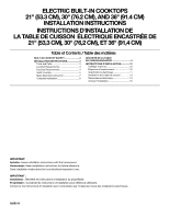
Whirlpool RCS2002RS Installation Instructions - Page 6
Installing Brackets Before Placing Cooktop in Cutout - installation
 |
UPC - 050946997087
View all Whirlpool RCS2002RS manuals
Add to My Manuals
Save this manual to your list of manuals |
Page 6 highlights
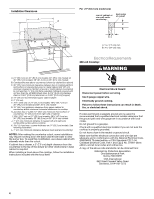
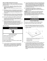
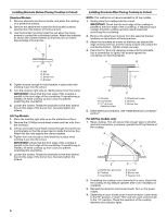
Installing Brackets Before Placing Cooktop in Cutout: Standard Models 1. Remove elements and burner bowls, and place the cooktop on a protective surface. 2. Remove the attachment screws for the bracket locations selected from the bottom of the burner box. 3. Use the bracket mounting holes that will allow the clamp screws to contact the countertop bottom. Attach the brackets as shown then rotate brackets so that they do not extend beyond edge of burner box. B A D C A. Nut B. Screw C. Burner box D. Bracket 4. Tighten screws enough to hold brackets in place when the cooktop is put into the cutout. 5. Turn the cooktop right side up. Gently place it into the cutout. IMPORTANT: Check that the front edge of the cooktop is parallel to the front edge of the countertop. If repositioning is needed, lift entire cooktop up from cutout to prevent scratching the countertop. 6. Loosen the screws. Rotate the brackets so that they extend beyond the edge of the burner box. Securely tighten the screws. Lift Top Models 1. Place the cooktop right side up on the protective surface. 2. Remove the 2 Phillips round-head screws and hex nuts from the envelope. 3. Lift top and install round-head screws through the burner box and brackets so that the screw head is inside the burner box. Attach the hex nuts against the clamp brackets. 4. Tighten hex nuts enough to hold brackets in place when cooktop is put into the cutout. IMPORTANT: Check that the front edge of the cooktop is parallel to the front edge of the countertop. If repositioning is needed, lift entire cooktop up from cutout to prevent scratching the countertop. 5. Loosen the screws. Rotate the brackets so that they extend beyond the edge of the burner box. Securely tighten the screws . Installing Brackets After Placing Cooktop in Cutout: NOTE: This method is not recommended for lift top models. 1. Gently place the cooktop into the cutout. IMPORTANT: Check that the front edge of the cooktop is parallel to the front edge of the countertop. If repositioning is needed, lift entire cooktop up from cutout to prevent scratching the countertop. 2. Remove the attachment screws from the selected bracket locations on the bottom of the burner box. 3. Attach the brackets as shown so that they are beyond the edge of the burner box and the clamp screws will contact the countertop bottom. Tighten screws securely. 4. Place the 2¹⁄₂" (6.4 cm) clamping screws into the brackets. Use a screwdriver to tighten the screws against the countertop. Do Not Overtighten. A B F C E D A. Cooktop B. Countertop C. 2¹⁄₂" (6.4 cm) clamping screw D. Attachment screw E. Bracket F. Burner box 5. Make electrical connection. See "Make Electrical Connection" section." For Lift Top models only: 1. Raise cooktop. This will ensure that enough slack is left after electrical connection to properly operate the lift top feature of the cooktop. A B F C E D A. Switch box and cover B. Cooktop C. Countertop D. Conduit E. Burner box F. Support rod 2. If installing the cooktop over a lower built-in oven, check that the cooktop lift top feature operates after oven installlation is complete. 3. Reinstall the elements and burner bowls. Turn on the power supply. 4. Depending on your model, push in and turn each control knob to the"HI" position or touch "ON" and turn each control knob to the "HI" position. Check the operation of the cooktop elements and indicator lights. 6
-
 1
1 -
 2
2 -
 3
3 -
 4
4 -
 5
5 -
 6
6 -
 7
7 -
 8
8 -
 9
9 -
 10
10 -
 11
11 -
 12
12 -
13
-
14
-
15
-
16
 |
 |
