Whirlpool WFE510S0AS Installation Guide - Page 12
Verify Anti-Tip Bracket Is Installed and, Engaged - replacement top
 |
View all Whirlpool WFE510S0AS manuals
Add to My Manuals
Save this manual to your list of manuals |
Page 12 highlights
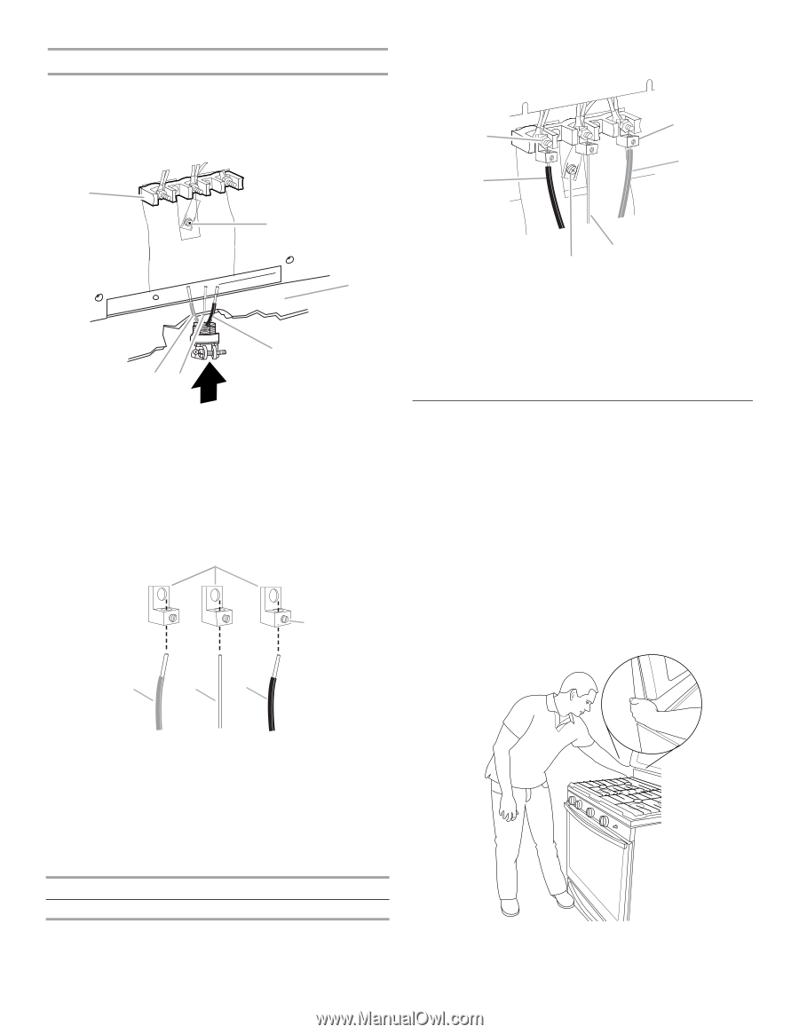
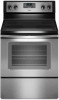
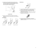
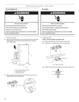
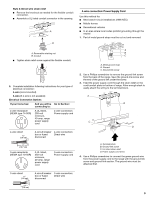
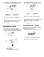
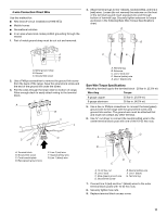
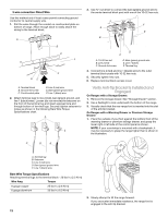
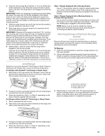
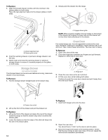
3-wire connection: Direct Wire Use this method only if local codes permit connecting ground conductor to neutral supply wire. 1. Pull the wires through the conduit on cord/conduit plate on bottom of range. Allow enough slack to easily attach the wiring to the terminal block. A 3. Use ³⁄₈" nut driver to connect the bare (green) ground wire to the center terminal block post with one of the 10-32 hex nuts. F A E B B C F DE A. Terminal block B. Ground-link screw C. Cord/conduit plate D. Line 2 (red) wire E. Bare (green) ground wire F. Line 1 (black) wire 2. Attach terminal lugs to line 2 (red), bare (green) ground, and line 1 (black) wires. Loosen (do not remove) the setscrew on the front of the terminal lug and insert exposed wire end through bottom of terminal lugs. Securely tighten setscrew to torque as shown in the following Bare Wire Torque Specifications chart. A B D C A. 10-32 hex nut B. Line 2 (red) C. Ground-link screw D. Bare (green) ground wire E. Line 1 (black) F. Terminal lug 4. Connect line 2 (red) and line 1 (black) wires to the outer terminal block posts with 10-32 hex nuts. 5. Securely tighten hex nuts. 6. Replace terminal block access cover. Verify Anti-Tip Bracket Is Installed and Engaged On Ranges with a Storage Drawer: 1. Remove the storage drawer. See "Storage Drawer" section. 2. Use a flashlight to look underneath the bottom of the range. 3. Visually check that the rear range foot is inserted into the slot of the anti-tip bracket. On Ranges with a Warming Drawer or Premium Storage Drawer: 1. Place the outside of your foot against the bottom front of the warming drawer or premium storage drawer, and grasp the lower right or left side of the control panel as shown. NOTE: If your countertop is mounted with a backsplash, it may be necessary to grasp the range higher than is shown in the illustration. C D E A. Terminal lug B. Setscrew C. Line 2 (red) wire D. Bare (green) ground wire E. Line 1 (black) wire Bare Wire Torque Specifications Attaching terminal lugs to the terminal block - 20 lbs-in. (2.3 N-m) Wire Awg Torque 8 gauge copper 25 lbs-in. (2.8 N-m) 6 gauge aluminum 35 lbs-in. (4.0 N-m) 2. Slowly attempt to tilt the range forward. If you encounter immediate resistance, the range foot is engaged in the anti-tip bracket. 12
-
 1
1 -
2
-
3
-
4
-
5
-
6
-
 7
7 -
 8
8 -
 9
9 -
 10
10 -
 11
11 -
 12
12 -
 13
13 -
 14
14 -
 15
15 -
 16
16
 |
 |