Whirlpool WFE510S0AS Installation Guide - Page 7
Floor Mounting, Wall Mounting - electric range
 |
View all Whirlpool WFE510S0AS manuals
Add to My Manuals
Save this manual to your list of manuals |
Page 7 highlights
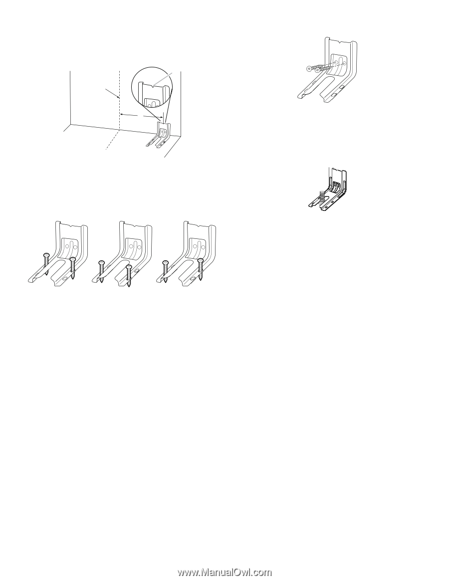
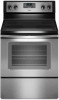
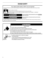
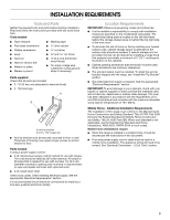
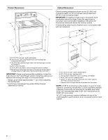
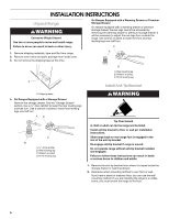
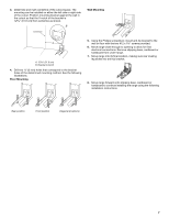
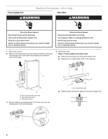
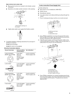
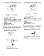
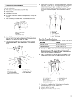
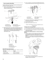
3. Determine and mark centerline of the cutout space. The mounting can be installed on either the left side or right side of the cutout. Position mounting bracket against the wall in the cutout so that the V-notch of the bracket is 12 31.9 cm) from centerline as shown. B Centerline Wall Mounting A A. 12 31.9 cm) B. Bracket V-notch 4. Drill two ¹⁄₈" (3 mm) holes that correspond to the bracket holes of the determined mounting method. See the following illustrations. Floor Mounting 5. Using the Phillips screwdriver, mount anti-tip bracket to the wall or floor with the two #12 x 1⁵⁄₈" screws provided. 6. Move range close enough to opening to allow for final electrical connections. Remove shipping base, cardboard or hardboard from under range. 7. Move range into its final location, making sure rear leveling leg slides into anti-tip bracket. 8. Move range forward onto shipping base, cardboard or hardboard to continue installing the range using the following installation instructions. Rear position Front position Diagonal (2 options) 7
-
 1
1 -
 2
2 -
 3
3 -
 4
4 -
 5
5 -
 6
6 -
 7
7 -
 8
8 -
 9
9 -
 10
10 -
 11
11 -
 12
12 -
13
-
14
-
15
-
16
 |
 |