Whirlpool WML75011HN Installation Instructions
Whirlpool WML75011HN Manual
 |
View all Whirlpool WML75011HN manuals
Add to My Manuals
Save this manual to your list of manuals |
Whirlpool WML75011HN manual content summary:
- Whirlpool WML75011HN | Installation Instructions - Page 1
very important. We have provided many important safety messages in this manual and on your appliance. Always read and obey all safety if you don't immediately follow instructions. WARNING You can be killed or seriously injured if you don't follow instructions. All safety messages will tell - Whirlpool WML75011HN | Installation Instructions - Page 2
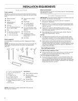
and parts before starting installation. Read and follow the instructions provided with any tools listed here. ■■ Measuring tape and minimum 3/8" (10 mm) thickness drywall or plaster/lath within cabinet opening. ■■ Support for weight of 150 lbs (68 kg) which includes microwave oven and items placed - Whirlpool WML75011HN | Installation Instructions - Page 3
Plug into a grounded 3 prong outlet. Do not remove ground prong. Do not use an adapter. Do not use an extension cord. Failure to follow these instructions can result in death, fire, or electrical shock. Observe all governing codes and ordinances. Required: ■ A 120-volt, 60 Hz, AC-only, 15- or 20-amp - Whirlpool WML75011HN | Installation Instructions - Page 4
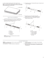
INSTALLATION INSTRUCTIONS Wall Venting Installation Only 1. Using diagonal wire cutting pliers, gently snip out the rectangular vent cover on the damper plate. Roof Venting Installation Only 1. Remove - Whirlpool WML75011HN | Installation Instructions - Page 5
3. Secure damper assembly with 2 sheet metal screws. Note: To ensure good performance of airflow, for Wall and Roof venting, remove the charcoal filter from the bottom plate before operating the microwave oven. 2. Place the vent cover C (removed from step 1) to area A, and rotate 180 degree. - Whirlpool WML75011HN | Installation Instructions - Page 6
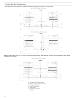
can be done. Wall Studs at End Holes Figure 3 B D A A,D E C C E F A. End holes (on mounting plate) B. Cabinet opening vertical centerline C. Wall stud centerlines D. Holes for lag screws E. Support tabs F. Mounting plate center markers 6 - Whirlpool WML75011HN | Installation Instructions - Page 7
the upper cabinet and must be on a level line with each other. They must each be 14¹⁄8" (35.9 cm) from the centerline. 5. With the support tabs facing forward (see illustrations in the "Locate Wall Stud(s)" section), align the mounting plate center markers to the centerline on the wall, making sure - Whirlpool WML75011HN | Installation Instructions - Page 8
section. For fast wall and roof vent installation, see the quick reference guide on the mounting plate. No Wall Studs at End Holes (Figures 1 the wall on atleast 1 wall stud as well as at both ends. 1. With the support tabs of the mounting plate facing forward, insert 3/16-24 x 3" round-head bolts - Whirlpool WML75011HN | Installation Instructions - Page 9
frame, against the upper cabinet bottom. The template has trim lines to use as guides ■■ If the wall behind the microwave oven (as installed) has a partial wall 3. Using 2 or more people, lift microwave oven and hang it on support tabs at the bottom of mounting plate. NOTE: To avoid damage to the - Whirlpool WML75011HN | Installation Instructions - Page 10
has not tripped. Replace the fuse or reset the circuit breaker. If the problem continues, call an electrician. ■ Check that the power supply cord is plugged into a grounded 3 prong outlet. ■ See the User Instructions for troubleshooting information. Installation is now complete. Save Installation - Whirlpool WML75011HN | Installation Instructions - Page 11
VENTING DESIGN SPECIFICATIONS This section is intended for architectural designer and builder/ contractor reference only. NOTES: A ■■ Vent materials needed for installation are not provided with microwave hood combination. ■■ We do not recommend using a flexible metal vent. B ■■ To avoid - Whirlpool WML75011HN | Installation Instructions - Page 12
6 ft (1.8 m) straight = 8 ft (2.4 m) ASSISTANCE Call your authorized dealer or service center. When you call, you will need the microwave oven model number and serial number , call us at our toll-free number listed in the User Guide. Following is a list of available replacement parts. You will need
-
 1
1 -
 2
2 -
 3
3 -
 4
4 -
 5
5 -
 6
6 -
 7
7 -
8
-
9
-
10
-
11
-
12
 |
 |
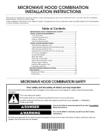
MICROWAVE HOOD COMBINATION
INSTALLATION INSTRUCTIONS
Table of Contents
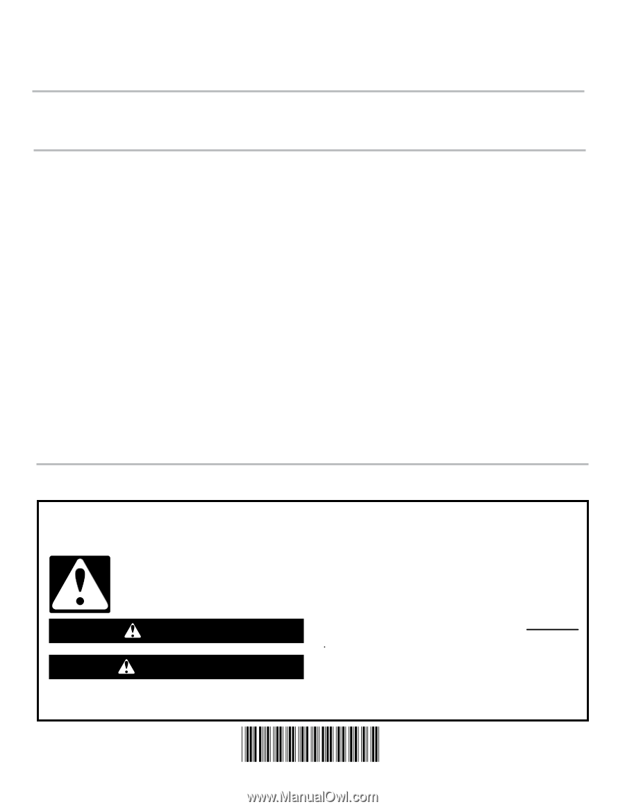
MICROWAVE HOOD COMBINATION SAFETY
You can be killed or seriously injured if you don't immediately
You
can be killed or seriously injured if you don't follow
All safety messages will tell you what the potential hazard is, tell you how to reduce the chance of injury, and tell you what can
happen if the instructions are not followed.
Your safety and the safety of others are very important.
We have provided many important safety messages in this manual and on your appliance. Always read and obey all safety
messages.
This is the safety alert symbol.
This symbol alerts you to potential hazards that can kill or hurt you and others.
All safety messages will follow the safety alert symbol and either the word “DANGER” or “WARNING.”
These words mean:
follow instructions.
instructions.
DANGER
WARNING
MICROWAVE HOOD COMBINATION SAFETY
..............................
1
INSTALLATION REQUIREMENTS
.................................................
2
Tools and Parts
.............................................................................
2
Location Requirements
.................................................................
2
Product Dimensions
......................................................................
3
Electrical Requirements
................................................................
3
INSTALLATION INSTRUCTIONS
....................................................
4
Wall Venting Installation Only
........................................................
4
Install Damper Assembly (for wall venting only)
...........................
4
Roof Venting Installation Only
........................................................
4
Install Damper Assembly (for roof venting only)
............................
4
Vent Cover Installation
...................................................................
5
Locate Wall Stud(s)
........................................................................
5
Mark Rear Wall
...............................................................................
7
Drill Holes in Rear Wall
...................................................................
8
Attach Mounting Plate to Wall
........................................................
8
Prepare Upper Cabinet
...................................................................
9
Install the Microwave Oven
............................................................
9
Complete Installation
......................................................................
10
VENTING DESIGN SPECIFICATIONS
..............................................
11
ASSISTANCE
.....................................................................................
12
Replacement Parts
.........................................................................
12
Accessories
.....................................................................................
12
This product is suitable for use above electric or gas cooking products up to and including 36" (91.4 cm) wide. See the “Installation
Requirements” section for further notes.
These installation instructions cover different models. The appearance of your particular model may differ slightly from the illustration
in these installation instructions.
W11124888B