Whirlpool WML75011HN Installation Instructions - Page 7
Mark Rear Wall
 |
View all Whirlpool WML75011HN manuals
Add to My Manuals
Save this manual to your list of manuals |
Page 7 highlights
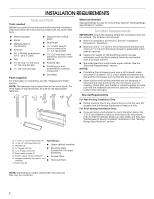
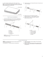
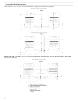
Wall Studs at End Holes Figure 4 B A,D A,D E C C E F A. End holes (on mounting plate) B. Cabinet opening vertical centerline C. Wall stud centerlines D. Holes for lag screws E. Support tabs F. Mounting plate center markers Mark Rear Wall The microwave oven must be installed on a minimum of 1 wall stud, preferably 2, using a minimum of 1 lag screw, preferably 2. 1. Using measuring tape, find and clearly mark the vertical centerline of the opening. 3. Holding the mounting template in place, mark both holes in the lower corners and draw a horizontal line across the bottom edge of the mounting template. These represent the mounting plate's end holes and bottom edge. 4. Remove the mounting template and check the markings: Upper cabinet bottom A 15³⁄₄" (40.0 cm) Centerline 17¹⁄₄" (43.8 cm) A. Centerline 2. Align the center markers on the mounting plate to the centerline on the wall, making sure it is level, and that the top of the mounting plate is butted up against the bottom edge of the upper cabinet. NOTES: ■ If the front edge of the upper cabinet is lower than the back edge, lower the mounting plate so that its top is level with the front edge of the cabinet. ■ If the mounting template is damaged or unusable, measure and mark the wall with the dimensions described in Step 4. D A C B 14¹⁄₈" (35.9 cm) 14¹⁄₈" (35.9 cm) Mounting plate end hole Bottom of mounting plate ■■ The bottom edge line must be 17¹⁄4" (43.8 cm) from the bottom of the upper cabinet and must be level. ■■ The end holes must be 15³⁄4" (40.0 cm) from the bottom edge of the upper cabinet and must be on a level line with each other. They must each be 14¹⁄8" (35.9 cm) from the centerline. 5. With the support tabs facing forward (see illustrations in the "Locate Wall Stud(s)" section), align the mounting plate center markers to the centerline on the wall, making sure its bottom edge is aligned to the horizontal line drawn in Step 3 and that the end holes are properly marked. Make sure the mounting plate is level. 6. Holding the mounting plate in place, find the wall stud centerline(s) drawn in Step 2 of "Locate Wall Stud(s)" and mark at least 1, preferably 2 hole(s) through the mounting plate, closest to the wall stud centerline(s). See figures 1, 2, and/or 3 in "Possible Wall Stud Configurations" in the "Locate Wall Stud(s)" section. The blackened holes in the shaded areas are ideal hole locations. 7. Set the mounting plate aside. A. Rear wall B. Mounting Template C. Top of mounting template must align with front edge of cabinet D. Front edge of upper cabinet 7
-
 1
1 -
 2
2 -
 3
3 -
 4
4 -
 5
5 -
 6
6 -
 7
7 -
 8
8 -
 9
9 -
 10
10 -
 11
11 -
 12
12
 |
 |
