Whirlpool WML75011HN Installation Instructions - Page 8
Drill Holes in Rear Wall, Attach Mounting Plate to Wall
 |
View all Whirlpool WML75011HN manuals
Add to My Manuals
Save this manual to your list of manuals |
Page 8 highlights
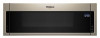
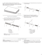
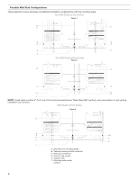
Wall Venting Installation Only Upper cabinet bottom 4" (10.2 cm) Centerline ³⁄₈" (1 cm) 6" (15.2 cm) 6" (15.2 cm) 8. Mark the centerline 3/8" (1 cm) down from the bottom edge of the upper cabinet. 9. Using measuring tape, measure out 6" (15.2 cm) on both sides of the centerline, and mark. 10. Measure down 4" (10.2 cm) from the mark made in step 8 and mark. 11. Using a straightedge, draw the 2 horizontal, level lines through the marks made in steps 8 and 10. 12. Draw the 2 vertical plumb lines down from the marks made in step 9 to complete the 12" x 4" (30.5 x 10.2 cm) rectangle. This is the venting cutout area. 13. Cut a ³⁄4" (19 mm) hole in one corner of the cutout area. 14. Using a keyhole saw, cut out the venting cutout area. Attach Mounting Plate to Wall NOTE: Secure the mounting plate to the wall at both end holes drilled into the wall studs and/or drywall using either 3/16-24 x 3" round-head bolts and toggle nuts or 1/4" x 2" lag screws. Refer to illustrations in "Possible Wall Stud Configurations" in the "Locate Wall Stud(s)" section. For fast wall and roof vent installation, see the quick reference guide on the mounting plate. No Wall Studs at End Holes (Figures 1 and 2) NOTE: The mounting plate must be secured to the wall on atleast 1 wall stud as well as at both ends. 1. With the support tabs of the mounting plate facing forward, insert 3/16-24 x 3" round-head bolts through both end holes of mounting plate. 2. Start toggle nuts on bolts from the back of the mounting plate. Leave enough space for the toggle nuts to go through the wall and to open. B A C Drill Holes in Rear Wall In addition to being installed on at least 1 wall stud, the mounting plate must attach to the wall at both end holes. If the end holes are not over wall studs, use two 3/16-24 x 3" round head bolts with toggle nuts; if 1 end hole is over a wall stud, use 1 lag screw and one 3/16-24 x 3" round-head bolt with toggle nut; or if both end holes are over wall studs, use 2 lag screws. Following are 3 installation configurations. Installation for No Wall Studs at End Holes (Figures 1 and 2) A. 3/16-24 x 3" round-head bolt B. Mounting plate C. Spring toggle nut 3. Position mounting plate on the wall. 4. Push the 2 bolts with toggle nuts through the drywall and finger tighten the bolts to make sure toggle nuts have opened against drywall. 1. Drill 5/8" (16 mm) holes through the wall at both end holes C marked in Step 3 of "Mark Rear Wall." A 2. Drill 3/16" (5 mm) hole(s) into the wall stud(s) at the hole(s) marked in Step 6 of "Mark Rear Wall." Refer to figures 1 and 2 in "Possible Wall Stud Configurations" in the "Locate Wall B Stud(s)" section. D Installation for Wall Stud at One End Hole (Figure 3) 1. Drill a 3/16" (5 mm) hole into the wall stud at the end hole marked in Step 3 of "Mark Rear Wall." 2. If installing on a second wall stud, drill a 3/16" (5 mm) hole into the wall stud at the other hole marked in Step 6 of "Mark Rear Wall." Refer to Figure 3 in "Possible Wall Stud Configurations" in the "Locate Wall Stud(s)" section. 3. Drill a 5/8" (16 mm) hole through the wall at the other end hole. Installation for Wall Studs at Both End Holes (Figure 4) 1. Drill 3/16" (5 mm) hole into the wall stud at the end hole marked in Step 3 of "Mark Rear Wall. A. 3/16-24 x 3" round-head bolt B. Mounting plate C. Spring toggle nut D. Drywall 5. Insert lag screw(s) into the hole(s) drilled into wall stud(s) in Step 2 of "Installation for No Wall Studs at End Holes" in the "Drill Holes in Rear Wall" section. 6. Check alignment of mounting plate, making sure it is level. 7. Securely tighten all lag screws and bolts. Wall Stud at One End Hole (Figure 3) 1. With the support tabs of the mounting plate facing forward, insert a 3/16 -24 x 3" round-head bolt through the end hole that fits over the 5/8" (16 mm) hole drilled in Step 3 of "Installation for Wall Stud at One End Hole" in the "Drill Holes in Rear Wall" section. 2. Start a toggle nut on the bolt from the back of the mounting plate. Leave enough space for the toggle nut to go through the wall and to open. 8
-
 1
1 -
2
-
 3
3 -
 4
4 -
 5
5 -
 6
6 -
 7
7 -
 8
8 -
 9
9 -
 10
10 -
 11
11 -
 12
12
 |
 |
