Yamaha 01V96i Reference Manual - Page 153
COMP Parameter, Range, Description, THRESHOLD dB, RATIO, ATTACK ms, RELEASE ms, OUT GAIN dB
 |
View all Yamaha 01V96i manuals
Add to My Manuals
Save this manual to your list of manuals |
Page 153 highlights
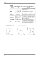
Appendix: Parameter Lists Dynamics Parameters 153 COMP Section COMP The COMP processor attenuates signals above a specified THRESHOLD by a specified RATIO. The COMP processor can also be used as a limiter, which, with a RATIO of :1, reduces the level to the threshold. This means that the limiter's output level never actually exceeds the threshold. Parameter Range Description THRESHOLD (dB) -54.0 to 0.0 (541 points) RATIO 1.0:1, 1.1:1, 1.3:1, 1.5:1, 1.7:1, 2.0:1, 2.5:1, 3.0:1, 3.5:1, 4.0:1, 5.0:1, 6.0:1, 8.0:1, 10:1, 20:1, :1 (16 points) ATTACK (ms) 0-120 (121 points) RELEASE (ms) OUT GAIN (dB) 44.1kHz: 6 ms - 46.0 sec 48kHz: 5 ms - 42.3 sec 88.2kHz: 3 ms - 23.0 sec 96kHz: 3 ms - 21.1 sec (160 points) 0.0 to +18.0 (180 points) KNEE Hard, 1-5 (6 points) This determines the level of input signal required to trigger the compressor. This determines the amount of compression, that is, the change in output signal level relative to change in input signal level. This determines how soon the signal will be compressed once the compressor has been triggered. This determines how soon the compressor returns to its normal gain once the trigger signal level drops below the threshold. The value is expressed as the duration required for the level to change by 6 dB. This sets the compressor's output signal level. This determines how compression is applied at the threshold. For higher knee settings, compression is applied gradually as the signal exceeds the specified threshold, creating a more natural sound. Output Level Input Level Output Level I/O Characteristics (KNEE=hard, OUT GAIN=0.0dB) THRESHOLD RATIO Time Series Analysis (RATIO=:1) Input signal THRESHOLD Output Signal ATTACK RELEASE Input Level Time Time 01V96i-Reference Manual
-
 1
1 -
2
-
3
-
4
-
5
-
6
-
7
-
8
-
9
-
10
-
11
-
12
-
13
-
14
-
15
-
16
-
17
-
18
-
19
-
20
-
21
-
22
-
23
-
24
-
25
-
26
-
27
-
28
-
29
-
30
-
31
-
32
-
33
-
34
-
35
-
36
-
37
-
38
-
39
-
40
-
41
-
42
-
43
-
44
-
45
-
46
-
47
-
48
-
49
-
50
-
51
-
52
-
53
-
54
-
55
-
56
-
57
-
58
-
59
-
60
-
61
-
62
-
63
-
64
-
65
-
66
-
67
-
68
-
69
-
70
-
71
-
72
-
73
-
74
-
75
-
76
-
77
-
78
-
79
-
80
-
81
-
82
-
83
-
84
-
85
-
86
-
87
-
88
-
89
-
90
-
91
-
92
-
93
-
94
-
95
-
96
-
97
-
98
-
99
-
100
-
101
-
102
-
103
-
104
-
105
-
106
-
107
-
108
-
109
-
110
-
111
-
112
-
113
-
114
-
115
-
116
-
117
-
118
-
119
-
120
-
121
-
122
-
123
-
124
-
125
-
126
-
127
-
128
-
129
-
130
-
131
-
132
-
133
-
134
-
135
-
136
-
137
-
138
-
139
-
140
-
141
-
142
-
143
-
144
-
145
-
146
-
147
-
 148
148 -
 149
149 -
 150
150 -
 151
151 -
 152
152 -
 153
153 -
 154
154 -
 155
155 -
 156
156 -
 157
157 -
 158
158 -
159
-
160
-
161
-
162
-
163
-
164
-
165
-
166
-
167
-
168
-
169
-
170
-
171
-
172
-
173
-
174
-
175
-
176
-
177
-
178
-
179
-
180
-
181
-
182
-
183
-
184
-
185
-
186
 |
 |
