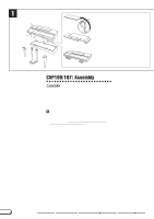
Yamaha 107 Reference Booklet - Page 61
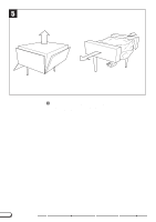
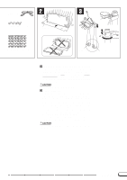
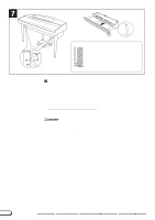
Carefully lean the main unit against a wall., Pedal assembly., MAKING SURE THAT IT CAN
 |
View all Yamaha 107 manuals
Add to My Manuals
Save this manual to your list of manuals |
Page 61 highlights
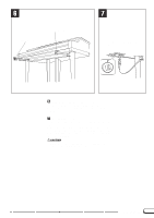
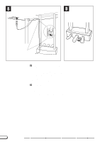
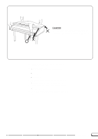
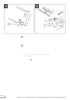
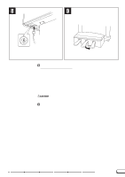
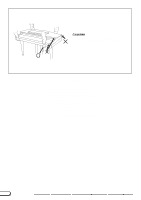
2 • AC power cord • 4 x 12 mm small screws x 4 • Blanket, etc. 3 B A C • 5 x 12 mm large screws x 30 • Right leg • Left leg XCarefully lean the main unit against a wall. To make it easier to install the legs, place a soft blanket or similar material on the floor near a wall, close the Clavinova keyboard cover, place the front panel of the Clavinova (the side with the keyboard) on the blanket and gently lean the unit against the wall - MAKING SURE THAT IT CAN NOT FALL - as shown in the illustration. CAUTION • Do not lay the main unit upside-down on the floor. C Pedal assembly. A: Under the pedal box, remove the vinyl tie from the pedal cable (the illustration shows the tie removed). Paying close attention to the direction of the rear legs (take note of the leg brackets in the illustration), slide the pedal box onto the left leg. B: Align the cut hole in the pedal box with the hole in the left leg and insert the cable into the hole on the left leg, pull the cable out of the top of the left leg. C: Align the screw holes, attach the two 4 x 12 millimeter small screws to 2 locations. (First tighten both screws loosely, once the position has been determined tighten firmly.) Use the same procedure (A, B and C) to attach the right leg.(However, the right leg is not equipped with a pedal cord.) CAUTION • When you lift the pedal box assembly, make sure that you lift by both legs. CVP-109/107/105/103/700 61
-
 1
1 -
2
-
3
-
4
-
5
-
6
-
7
-
8
-
9
-
10
-
11
-
12
-
13
-
14
-
15
-
16
-
17
-
18
-
19
-
20
-
21
-
22
-
23
-
24
-
25
-
26
-
27
-
28
-
29
-
30
-
31
-
32
-
33
-
34
-
35
-
36
-
37
-
38
-
39
-
40
-
41
-
42
-
43
-
44
-
45
-
46
-
47
-
48
-
49
-
50
-
51
-
52
-
53
-
54
-
55
-
 56
56 -
 57
57 -
 58
58 -
 59
59 -
 60
60 -
 61
61 -
 62
62 -
 63
63 -
 64
64 -
 65
65 -
 66
66 -
67
-
68
 |
 |
