Yamaha 24N DME64N/24N V1.2 Supplemental notes - Page 4
Designer only.
 |
View all Yamaha 24N manuals
Add to My Manuals
Save this manual to your list of manuals |
Page 4 highlights
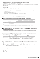
3. User Label Function Lets you attach names to assigned parameters. For details about settings, see the "DME Designer Version 1.2 Owner's Manual." ■ A GPI LOCK function has been added. This functions allows you to disable input from a GPI device. For details about settings, see the "DME Designer Version 1.2 Owner's Manual." ■ The number of MY16-C cards that can be used simultaneously in the DME64N is now four. In Version 1.0, only two MY16-C cards could be used simultaneously in the DME64N (page 20 in the DME64N/24N Owners Manual). In Version 1.1, up to four cards can be used simultaneously. However, if the serial number written on the upper surface of your DME64N is shown below, a hardware upgrade is needed. KK, KL, KM, KN, KO, KP, KX, KY are the third and fourth digits of the serial number. A fee is charged for the hardware upgrade. For details, contact Yamaha customer support using the contact information located at the end of the "DME64N/24N Owner's Manual." ■ The [PHONES] terminal can now be muted. The [PHONES] terminal in Version 1.0 was not muted when the unit as a whole was muted by pressing the [MUTE] button (page 40 in the DME64N/24N Owner's Manual, "Mute Switching." In Version 1.1, all outputs are muted including [PHONES]. ■ The CASCADE setting (page 53 in the DME64N/24N Owner's Manual) is now available from DME Designer only. In Version 1.0, CASCADE could be set in the DME64N, but in Version 2.0, this is a screen display function only. Set CASCADE from DME Designer. For details about settings, see the "DME Designer Version 1.2 Owner's Manual." ■ The monitoring function (page 42 in the DME64N/24N Owner's Manual) has been changed. • By editing the Monitoring Point List in DME Designer, you can select user-defined monitoring points in the DME64N/24N. Using this function, component input/output points can be selected for monitoring points in the DME64N/24N. • The [MONITOR] indicator blinks when you are using the probe monitor function to select monitoring points from DME Designer. • You can turn the monitoring function OFF. • Lighting of the indicator lamp is linked to ON/OFF for the monitoring function and probe monitoring function. The monitoring function is for monitoring the sound at a specific point within the DME. The monitored sound is output from the [PHONES] terminal and from the Monitor OUT that is set in DME Designer. 1. Setting a monitoring point from the DME64N/24N You can select a monitoring point in the DME64N/24N and check the sound. (1) Slot or user defined selection Select the slot or User Defined in the monitoring slot dialog. The following five position types can be selected: 1 Slot input/output terminal 2 CASCADE input/output terminal (DME64N only) 3 IN terminal (DME24N only) 4 OUT terminal (DME24N only) 5 User Defined By connecting 1 through 4 in DME Designer, you will be able to select the input/output terminal. You will be able to select 5 by editing the Monitoring Point List in DME Designer. (2) Selecting a Monitoring Point Monitoring points can be selected using the "Monitoring Point" dialog box. The monitoring point will switch and the [MONITOR] indicator lights up. Method of Operation With the monitoring function set to OFF ([MONITOR] indicator not lit) press the [MONITOR] button to display the Monitoring Slot Dialog. In the dialog, select the Monitoring Slot and Monitoring Point and use the [ENTER] button to confirm. Pressing the [CANCEL] button returns to the previous dialog. 4 Notes for DME64N/DME24N Version 1.2
-
 1
1 -
 2
2 -
 3
3 -
 4
4 -
 5
5 -
 6
6 -
 7
7 -
 8
8
 |
 |
