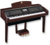
Yamaha CVP-309PM Owner's Manual - Page 207
Set the voltage selector and connect the power
 |
View all Yamaha CVP-309PM manuals
Add to My Manuals
Save this manual to your list of manuals |
Page 207 highlights
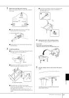
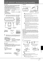
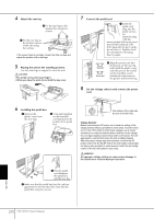
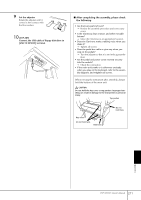
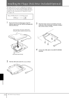
2 Attach two front legs and a rear leg. Refer to the diagram below to verify the orientation of the legs. Rear leg Front leg Front leg 4 Attach the cord holder on the unit as shown in the illustration below, then use the cord holder to affix the pedal cord. 3 1 Install and tighten four screws on each leg, starting with one of the front legs. 4 6 × 40 mm fixing screws 2 Slowly tilt the main unit forward until front legs reach the floor. 3 Install the pedal box. 1 Remove the twist tie that affixes the pedal cord to the upper portion of the pedal box. 4 Raising the unit to the standing position. Use the front legs as support to raise the unit. CAUTION • Be careful not to pinch your fingers. • When you raise the unit, do not hold the key cover. Twist tie 2 Align the cord with the groove on the unit, and attach the pedal box using four screws. 5 Set the voltage selector and connect the power cord. 127 110 Appendix 220 6 × 20 mm fixing screws 3 Insert the pedal cord plug into the pedal connector. Insert the plug so the arrow side faces front (toward the keyboard). If the plug will not go in easily, do not force it. Double-check the orientation of the plug, then try again. 240 Left of the rear leg on the bottom of the main unit, when viewed from front CVP-309/307 Owner's Manual 207
-
 1
1 -
2
-
3
-
4
-
5
-
6
-
7
-
8
-
9
-
10
-
11
-
12
-
13
-
14
-
15
-
16
-
17
-
18
-
19
-
20
-
21
-
22
-
23
-
24
-
25
-
26
-
27
-
28
-
29
-
30
-
31
-
32
-
33
-
34
-
35
-
36
-
37
-
38
-
39
-
40
-
41
-
42
-
43
-
44
-
45
-
46
-
47
-
48
-
49
-
50
-
51
-
52
-
53
-
54
-
55
-
56
-
57
-
58
-
59
-
60
-
61
-
62
-
63
-
64
-
65
-
66
-
67
-
68
-
69
-
70
-
71
-
72
-
73
-
74
-
75
-
76
-
77
-
78
-
79
-
80
-
81
-
82
-
83
-
84
-
85
-
86
-
87
-
88
-
89
-
90
-
91
-
92
-
93
-
94
-
95
-
96
-
97
-
98
-
99
-
100
-
101
-
102
-
103
-
104
-
105
-
106
-
107
-
108
-
109
-
110
-
111
-
112
-
113
-
114
-
115
-
116
-
117
-
118
-
119
-
120
-
121
-
122
-
123
-
124
-
125
-
126
-
127
-
128
-
129
-
130
-
131
-
132
-
133
-
134
-
135
-
136
-
137
-
138
-
139
-
140
-
141
-
142
-
143
-
144
-
145
-
146
-
147
-
148
-
149
-
150
-
151
-
152
-
153
-
154
-
155
-
156
-
157
-
158
-
159
-
160
-
161
-
162
-
163
-
164
-
165
-
166
-
167
-
168
-
169
-
170
-
171
-
172
-
173
-
174
-
175
-
176
-
177
-
178
-
179
-
180
-
181
-
182
-
183
-
184
-
185
-
186
-
187
-
188
-
189
-
190
-
191
-
192
-
193
-
194
-
195
-
196
-
197
-
198
-
199
-
200
-
201
-
 202
202 -
 203
203 -
 204
204 -
 205
205 -
 206
206 -
 207
207 -
 208
208 -
 209
209 -
 210
210 -
 211
211 -
 212
212 -
213
-
214
-
215
-
216
-
217
-
218
-
219
-
220
-
221
-
222
-
223
-
224
 |
 |
