Yamaha DPX-1100 Owner's Manual
Yamaha DPX-1100 Manual
 |
View all Yamaha DPX-1100 manuals
Add to My Manuals
Save this manual to your list of manuals |
Yamaha DPX-1100 manual content summary:
- Yamaha DPX-1100 | Owner's Manual - Page 1
- Yamaha DPX-1100 | Owner's Manual - Page 2
INSTRUCTIONS CAUTION RISK OF ELECTRIC SHOCK DO NOT OPEN CAUTION: TO REDUCE THE RISK OF ELECTRIC SHOCK, DO NOT REMOVE COVER (OR BACK). NO USER-SERVICEABLE PARTS INSIDE. REFER SERVICING TO QUALIFIED SERVICE bottom of the unit. Retain this Owner's Manual in a safe place for future reference. OBSERVERA - Yamaha DPX-1100 | Owner's Manual - Page 3
Yamaha Electronics Corporation 6660 Orangethorpe Avenue Buena Park, CA90620 714-522-9105 714-670-0108 Projector DPX-1100 operation. See the user manual instructions if interference to radio OFF" and "ON", please try to eliminate the problem by using one of the following measures: Relocate either - Yamaha DPX-1100 | Owner's Manual - Page 4
. Follow the lamp replacement procedure described in this manual. For U.K. customers If the socket outlets in the home are not suitable for the plug supplied with this appliance, it should be cut off and an appropriate 3 pin plug fitted. For details, refer to the instructions described below. Note - Yamaha DPX-1100 | Owner's Manual - Page 5
to computer devices .......... 47 10 Installation 48 Setting up the DPX-1100 48 Projection distance 49 Projection image position 50 11 Reference 51 Glossary 51 Compatible signal types 53 Maintenance 54 Troubleshooting 56 Message display 58 LED Indicator meanings 59 Specifications 60 - Yamaha DPX-1100 | Owner's Manual - Page 6
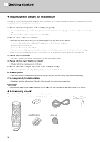
in your package. • Remote control • Batteries (AA, UM-3 or R6) • Power cable • Trigger-out DC plug (For USA only) AUTO V. POS ZOOM FOCUS IRIS SETTING PATT ESCAPE MENU ASPECT INPUT RESET HIDE STILL LIGHT S VIDEO A HDMI VIDEO B D4 INPUT MEMORY 1 2 3 4 5 6 • Pin/BNC - Yamaha DPX-1100 | Owner's Manual - Page 7
completely digitally processed images. Compatible with the content protection function of HDCP. Intelligent memory functions The DPX-1100 can store six image memory settings, called memory numbers, for each input jack. For each memory number, you can set parameters for different input resolutions - Yamaha DPX-1100 | Owner's Manual - Page 8
remote control sensor STANDBY/ON indicator Exhaust vent Lens Lens cap Adjustable feet Makes small adjustments to the projection angle Lamp cover Ventilation inlet 1 2 3 4 5 1 STANDBY/ON ESCAPE MENU PATTERN SETTING ASPECT INPUT LAMP COVER TEMP FAN DIGITAL CINEMA PROJECTOR DPX-1100 - Yamaha DPX-1100 | Owner's Manual - Page 9
panel / Connections> Controls and functions 3 Rear remote control sensor q w er INPUT B HDMI INPUT A OUT IN REMOTE RS-232C TRIGGER OUT RGB/YPBPR/YCBCR D4 VIDEO G/Y B/PB/CB R/PR/CR HD/SYNC VD S VIDEO VIDEO 1 2 3 45 6 7 8 90 1 INPUT B (D-sub 15 pin) Receives component video - Yamaha DPX-1100 | Owner's Manual - Page 10
8 ASPECT 9 RESET 0 STILL INPUT i o HIDE p LIGHT S VIDEO A HDMI q VIDEO B D4 INPUT MEMORY 1 2 3 w 4 5 6 1 Transmit indicator Lights up when the remote control sends infrared signals to the main unit. 2 AUTO button Automatically sets the DPX-1100 to the best settings for the - Yamaha DPX-1100 | Owner's Manual - Page 11
you do not perform any operation within 10 seconds. p HIDE button Temporarily halts projection of the image the DPX-1100 is currently displaying. Press again to cancel this effect. a Remote control code switch The remote control functions when the code set in the menu is the same as that set on the - Yamaha DPX-1100 | Owner's Manual - Page 12
control the DPX-1100 without having to be within range of the remote sensor. AUTO ESCAPE V.POS IRIS ZOOM SETTING FOCUS PATT MENU ID-1 STILL RESET ASPECT INPUT ID-2 S VIDEO HIDE VIDEO A B LIGHT HDMI 4 1 2MEMORYINPUT D4 5 3 6 INPUT B HDMI INPUT A OUT IN REMOTE RS-232C - Yamaha DPX-1100 | Owner's Manual - Page 13
sensor 7m (approximate value) Angle to sensor 30˚ vertically and horizontally (approximate value) INPUT B HDMI INPUT A OUT IN REMOTE RS-232C TRIGGER OUT RGB/YPBPR/YCBCR D4 VIDEO G/Y B/PB/CB R/PR/CR HD/SYNC VD S-VIDEO VIDEO AUTO V. POS ZOOM FOCUS IRIS SETTING PATT ESCAPE MENU - Yamaha DPX-1100 | Owner's Manual - Page 14
5 Preparation Before projection, install the main unit and a screen, connect the main unit to an AV component or computer, and adjust the projection image. You can begin projection as soon as installation is complete. Refer to the sections below for information on how to install the main unit to - Yamaha DPX-1100 | Owner's Manual - Page 15
a computer page 46 Step3 Turn the power on and selecting an image for projection • Turn on the projector power 5 • Begin playback of the input image • Select an input signal • Select a projection image aspect • Adjust the image Focus/Vertical and Horizontal position/Size/Iris page 12 - Yamaha DPX-1100 | Owner's Manual - Page 16
the main unit power turned on? Is the screen installed correctly? "Setting up the projector and screen" page 48 Image source component STANDBY /ON PURE DIRECT 2CH/MULTI CH INPUT SELECTOR SPEAKERS A B REC OUT/ZONE 2 SOURCE/REMOTE DTV/LD DVD CABLE MD/TAPE SAT CD-R VCR 1 CD VCR 2 DVR - Yamaha DPX-1100 | Owner's Manual - Page 17
main unit, then insert the plug into an AC outlet. The STANDBY/ON indicator lights orange. INPUT B HDMI INPUT A OUT IN REMOTE RS-232C TRIGGER OUT RGB/YPBPR/YCBCR D4 VIDEO G/Y B/PB/CB R/PR/CR HD/SYNC VD S-VIDEO VIDEO AC inlet button STANDBY/ON button 2. Press the STANDBY/ON button - Yamaha DPX-1100 | Owner's Manual - Page 18
message appears on the screen. Press again to enter standby. ASPECT INPUT Remote Control ASPECT INPUT LAMP COVER TEMP FAN Main unit 2. If you wish to place the DPX-1100 in standby mode, press the STANDBY/ON button again. The lamp changes to a half lit state, and the fan activates for - Yamaha DPX-1100 | Owner's Manual - Page 19
jack. : Selects RGB signals received from AV components connected to the INPUT B D-sub 15 pin jack. : Signals input to the HDMI jack from AV components (automatically distinguishes between component and RGB signals). : Selects digital component signals received from AV components connected to the - Yamaha DPX-1100 | Owner's Manual - Page 20
> Remote cotrol + button Main unit AUTO V. POS ZOOM FOCUS IRIS SETTING PATT ESCAPE MENU ASPECT INPUT RESET HDMI STILL LIGHT S VIDEO A DVI VIDEO B D4 INPUT MEMORY 1 2 3 4 5 6 STANDBY/ON ESCAPE MENU PATTERN SETTING button ASPECT INPUT LAMP COVER TEMP FAN INPUT - Yamaha DPX-1100 | Owner's Manual - Page 21
to project an image for an input signal. Remote cotrol Main unit AUTO V. POS INPUT ASPECT INPUT LAMP COVER TEMP FAN 1. Press the ASPECT button. The display aspect selection menu appears on the display. Display Aspect Ratio Auto Normal Squeeze Smart Zoom Zoom Special Through RESET HDMI - Yamaha DPX-1100 | Owner's Manual - Page 22
this case, manually select a suitable setting. Normal Projects images with their original display aspect. Depending on the input signal, HDTV for 16:9 images. Cinema Squeeze Removes the black bar from cinescope size screens for 4:3 images and resize the vertical image so that a 16:9 panel resolution - Yamaha DPX-1100 | Owner's Manual - Page 23
box Squeeze 14:9 image HDMI RGB PC All Normal Cinema Scope Normal Squeeze Display aspect Normal Smart Zoom Zoom Subtitle Zoom Cinema Zoom Squeeze Squeeze Cinema Squeeze 14:9 Zoom Normal Cinema Zoom Normal Normal Through Squeeze Through Selecting an input signal Projected image SUBTITLE 6 19 - Yamaha DPX-1100 | Owner's Manual - Page 24
INPUT LAMP COVER TEMP FAN Adjusting the vertical position - V.POS button If the center of the screen is not in line with the center of the lens of the DPX-1100 MENU SETTING button SETTING 1. Press the V.POS button on the remote control, or press the SETTING button on the main unit repeatedly - Yamaha DPX-1100 | Owner's Manual - Page 25
ESCAPE MENU Memo STANDBY/ON ESCAPE button ESCAPE PATTERN MENU SETTING button SETTING ASPECT INPUT LAMP COVER TEMP FAN • When you want to use the test pattern to adjust image focus press the PATT button on the remote control, or the PATTERN button on the main unit before carrying out step - Yamaha DPX-1100 | Owner's Manual - Page 26
DPX-1100 to suit your viewing environment by adjusting image quality, initial settings, defaults, and setup characteristics. These parameters can be accessed through the menu. Press the MENU button on the remote select. Menu operation guide Displays helpful instructions when special operations are - Yamaha DPX-1100 | Owner's Manual - Page 27
Status Initial 3 Color System INPUT A Signal INPUT A Sync Type INPUT B Signal INPUT B Sync Type HDMI Signal Auto Power Off Auto Input Search Display Language Lamp Running Time Reset 4 Setup 5 Location 9 6 Keystone Correction 6 Remote Control Sensor 10 7 6 Remote Control ID 11 6 Lens - Yamaha DPX-1100 | Owner's Manual - Page 28
Normal Squeeze Smart Zoom Zoom Special 4 Through 5 4: Signal Status Resolution Sync Type Sync Polarity Frequency Source Equipmet (HDMI only) Initial 5: Color System Auto NTSC NTSC4.43 PAL PAL-M PAL-N PAL60 SECAM 6: All Input Signals Component RGB PC RGB TV .etc 7: Display Language - Yamaha DPX-1100 | Owner's Manual - Page 29
• You can only select items displayed with a in advanced mode. You can adjust the image when the unit is receiving an input signal. Black Level (Input signal) Video/S-Video/Component/RGB TV Adjusts the level of darkness (black level) in an image. Adjusts the level of darkness without - Yamaha DPX-1100 | Owner's Manual - Page 30
the amount of red, giving a darker, more relaxed atmosphere to the image. Choices: 5,000 to 10,000 Color temprature adjustment White Correction (Input signal) Video/S-Video/Component/RGB TV/RGB PC Adjust in the [Color Adjustment] menu in advanced mode. Adjusts hUV. Increasing the hUV setting - Yamaha DPX-1100 | Owner's Manual - Page 31
Input limits of the projector. 0.5 W the remote control when Choices: 0 to 5 Iris (Input signal) Video/S-Video/Component/RGB TV Input signal) Component/RGB TV/RGB PC Adjusts the analog input signal gain and offset settings. Adjust the gain and offset for component and RGB (Y, CB, CR/R, G, B) input - Yamaha DPX-1100 | Owner's Manual - Page 32
unit receives at its composite input jacks. Choices: On/Off Reduces noise in analog images. Digital processing eliminates noise in the best color space coefficient for the image resolution. • [SDTV] : Color space coefficient for BT.601 type signal. • [HDTV] : Color space coefficient for BT. - Yamaha DPX-1100 | Owner's Manual - Page 33
Level (HDTV) (Input signal) Component/RGB TV Sync Adjustment (Input signal) RGB PC (except for HDMI signals) Tracking (Input signal) RGB PC (except for HDMI signals) Clamp Position (Input signal) Component/RGB TV Horiz. Display Position (Input signal) RGB PC (except for HDMI signals)/ Component - Yamaha DPX-1100 | Owner's Manual - Page 34
Type HDMI Signal Auto Power Off Auto Input Search Display Language Lamp Running Time Reset 30 Selects the color system to use for video input signals. Usually, set this parameter to Auto to have the unit automatically detect the signal and select an appropriate color system. Set the unit manually - Yamaha DPX-1100 | Owner's Manual - Page 35
the image. If you do not install the projector at right angles to the screen, the wider than the top Remote Control Sensor Remote Control ID Lens Adjustment Lock Lamp Power Menu Color Menu Advanced Selects whether to display memory number, input signal and other information on the projection screen - Yamaha DPX-1100 | Owner's Manual - Page 36
Remote Control 4 AUTO V. POS ZOOM FOCUS IRIS SETTING PATT ESCAPE MENU 5 ASPECT INPUT RESET HIDE STILL LIGHT S VIDEO A HDMI VIDEO B D4 INPUT menu entry screen, after moving a menu. 5 RESET button (Remote control only) Returns parameters back to their default settings (Does not - Yamaha DPX-1100 | Owner's Manual - Page 37
) MENU Button AUTO V. POS ZOOM FOCUS IRIS SETTING PATT ESCAPE MENU ASPECT INPUT STANDBY/ON ESCAPE MENU PATTERN SETTING ASPECT INPUT LAMP COVER TEMP FAN Remote Control Main Unit or Remote Control Main Unit 1. Open the menu screen. Image Move Menu Window Signal Initial - Yamaha DPX-1100 | Owner's Manual - Page 38
COVER TEMP FAN Main Unit MENU Button AUTO V. POS ZOOM FOCUS IRIS SETTING PATT ESCAPE MENU ASPECT INPUT Remote Control STANDBY/ON ESCAPE MENU PATTERN SETTING ASPECT INPUT LAMP COVER TEMP FAN Main Unit 5. Move to another item or group. Memo • Use the h / g buttons to move the - Yamaha DPX-1100 | Owner's Manual - Page 39
A Signal Input A Sync Type Input B Signal Input B Sync Type HDMI Signal Remote Control Sensor Remote Control ID 3. Use the cursor button to adjust item settings. Memo • You must press the button to confirm some settings. : Fix appears in the operations guide at the bottom left of the menu screen - Yamaha DPX-1100 | Owner's Manual - Page 40
Menu operations Special menu operations Some items in the menu require special methods to configure. 1. Select [Color Adjustment] in the [Image] group from the main menu. 2. Press the + button to enter submenus. 3. Select a suitable item from [Standard] • [WRGB] • [WRGBYCM] using - Yamaha DPX-1100 | Owner's Manual - Page 41
the default settings. 1. From the main menu, select the item you wish to reset to the default setting. 2. Press the RESET button on the remote control to reset to the default settings (resetting does not affect items with no default setting). Memo • The RESET button has a special function when used - Yamaha DPX-1100 | Owner's Manual - Page 42
INPUT A Signal INPUT A Sync Type INPUT B Signal INPUT B Sync Type HDMI Signal Auto Power Off Auto Input Search Display Language Lamp g buttons. Image Special Move Menu Window Signal Initial Setup Subtitle Zoom Cinema Zoom Cinema Squeeze 14:9 Zoom 4. Press the button. A appears to the right - Yamaha DPX-1100 | Owner's Manual - Page 43
Menu operations 5. Press the + button to enter lower level selection menus. 6. Use h or g buttons to select [Subtitle Area] or [V Scroll]. 7. Use the + or - buttons to select a suitable setting. Memo • Press h or g buttons to move to a different menu item within the [Subtitle Zoom] menu. 8. Press - Yamaha DPX-1100 | Owner's Manual - Page 44
of the inline menu. Inline menu item Parameter adjustment area The menu items available may differ depending on the input signal type. For video type sources Black Level White Level Gamma Hue Saturation Color Temp. White Correction Sharpness Type Sharpness Gain White - Yamaha DPX-1100 | Owner's Manual - Page 45
The DPX-1100 can store up to 6 sets of configurations, called memory numbers, for each input jack. For each memory number the DPX1100 stores SETTING PATT ESCAPE MENU ASPECT INPUT STANDBY/ON ESCAPE MENU PATTERN SETTING ASPECT INPUT LAMP COVER TEMP FAN Remote Control Main Unit 1. Select - Yamaha DPX-1100 | Owner's Manual - Page 46
memory setting number. or Remote Control Main Unit or Remote Control Main Unit 5. Press the button to call the memory number you selected. Memo • When the unit receives a signal with a different resolution from the same input jack, it detects the new resolution and calls an appropriate memory - Yamaha DPX-1100 | Owner's Manual - Page 47
information stored in its memory. You can set the lock function for each memory number, and additionally for each SDTV/HDTV/RGB-PC input. or Remote Control Main Unit 1. Select the memory number you wish to lock. 2. Select a memory number status. 3. Press the button. A mark - Yamaha DPX-1100 | Owner's Manual - Page 48
the currently selected input jack) to its default setting. 1. From the main menu, select [Initial] [Reset] [Current Image Memory]. Move Menu Window Signal Initial Setup or Remote Control Main Unit 2. Press the + button to display a confirmation screen. Reset + : Enter All Settings - Yamaha DPX-1100 | Owner's Manual - Page 49
the all memory contents to the default settings regardless of the input jack or input signal. 1. From the main menu, select [Initial] [Reset] [All Image memory]. Move Menu Window Signal Initial Setup or Remote Control Main Unit 2. Press the + button to display a confirmation screen - Yamaha DPX-1100 | Owner's Manual - Page 50
on the component you are attempting to connect. Refer to the owner's manual for the component. • Insert all plugs firmly to avoid noise or other problems. HDMI cable (digital) D connector cable INPUT B HDMI INPUT A OUT IN REMOTE RS-232C TRIGGER OUT RGB/YPBPR/YCBCR D4 VIDEO G/Y B/PB/CB - Yamaha DPX-1100 | Owner's Manual - Page 51
Signal type RGB (Analog) RGB (Analog) Connector type BNC jack x 5 D-sub 15 pin INPUT B HDMI INPUT A OUT IN REMOTE RS-232C TRIGGER OUT RGB/YPBPR/YCBCR D4 VIDEO G/Y B/PB/CB R/PR/CR HD/SYNC VD S VIDEO VIDEO Connection D-Sub monitor cable BNC monitor cable Monitor output terminal - Yamaha DPX-1100 | Owner's Manual - Page 52
10 Installation Setting up the DPX-1100 There are four ways of mounting the projector. Mounting method Placed on a table Mounted on to project and view the image from in front of the screen. The distance between the projector and the screen should be the same as "A: From in front of the screen". - Yamaha DPX-1100 | Owner's Manual - Page 53
information in the table below to determine the best location to place the projector in to suit your screen size. Screen of a few percent. 10 Installation Since the DPX-1100 has a 16:9 panel, the ideal installation location for use with a 4:3 - Yamaha DPX-1100 | Owner's Manual - Page 54
Projection image position Follow the instructions to adjust the position of the projected image aspect ratio may not be correctly maintained. To correctly maintain the aspect ratio, try to use the DPX1100 with the lens shift in the center position. • The video may be disturbed by keystone correction - Yamaha DPX-1100 | Owner's Manual - Page 55
projectors and image signals and their explanations. Please refer to it when using this manual Digital Light Processing, an image display engine used in projectors HDMI remote HDTV High-Definition Television, a term used to define systems that satisfy the following conditions: • A vertical resolution - Yamaha DPX-1100 | Owner's Manual - Page 56
Computers output signals with a given regular frequency, which you must synchronize the projector to in order to produce a good quality image. If you do not Faroudja, a division of Genesis Microchip, Inc. * HDMI, the HDMI logo and High-Definition Multimedia Interface are trademarks or registered trademark - Yamaha DPX-1100 | Owner's Manual - Page 57
75.000 85.008 56.250 60.317 72.188 75.000 85.061 60.004 66.666 HDMI Format (Component/RGB signals input from the HDMI jack) Signal type H active V active f (H) f (V) (pixels) (lines) (kHz) (Hz) VGA 640 480 31.469 59.94 480i (1440) 720 480 15.734 59.94 576i (1440) 720 - Yamaha DPX-1100 | Owner's Manual - Page 58
cloth to prevent scratching. 3. Press the filter hook on the underside of the main unit to remove the filter. 4. Firmly attach the new filter. The lamp does not light if the filter is incorrectly attached. Warning • Contact a YAMAHA dealer or service center if you require replacement filters. 54 - Yamaha DPX-1100 | Owner's Manual - Page 59
displayed on the screen. In this case, follow the instructions below to replace the lamp cartridge. Be sure to use the replacement lamp cartridge PJL 427. Other lamp cartridges are not suitable for use in the DPX-1100. Consult the store where the DPX1100 was bought for details on replacement of - Yamaha DPX-1100 | Owner's Manual - Page 60
Troubleshooting Problem Cause The DPX-1100 does not The power cable is not plugged in. turn on. You attempted to turn on The DPX-1100 immediately after turning it off. No picture. The filter cover is not correctly attached. The lamp cover is not correctly attached. The lens cover has not - Yamaha DPX-1100 | Owner's Manual - Page 61
Troubleshooting Problem COVER warning indicator lights up. Cause The filter cover is not correctly attached. The lamp cover is not correctly attached. LAMP warning indicator lights up or blinks. Lamp running time has exceeded 2000 hours. The lamp has burned out. TEMP warning indicator The - Yamaha DPX-1100 | Owner's Manual - Page 62
PC or HDMI signal currently being input. The unit is not able to decode the video signal currently being input. The unit power switch is turned on if the lamp running time replacement time. Please replace with the menu operation guide when you press an invalid button during menu operation. This message - Yamaha DPX-1100 | Owner's Manual - Page 63
LED indicator meanings LED indicator State STANDBY/ON (*) Unlit Lit orange Blinking green Lit green Blinking orange Blinking red LAMP Unlit Blinking orange Lit red COVER Unlit Lit red TEMP Unlit Lit red FAN Unlit Lit red Meaning Electrical fault. Standby Preparing for operation. - Yamaha DPX-1100 | Owner's Manual - Page 64
(without video signals) (480i, 576i, 480p, 576p) HDMI Digital RGB/component signal • Controls Remote RS-232C (D-sub 9 pins) Trigger +12 V/Max 200 mA when the power is on Wireless remote 1 in front, 1 at rear Wired remote 1 input jack, 1 output jack • General Usable temperature range - Yamaha DPX-1100 | Owner's Manual - Page 65
9"-3/8 SETTING 495 19"-1/2 DIGITAL CINEMA PROJECTOR DPX-1000 INPUT MENU LAMP COVER TEMP FAN STANDBY/ON ASPECT ESCAPE PATTERN (257.5 10"-1/8) 119.1 4"-3/5 124.6 4"-7/8 465.4 18"-5/16 132.1 5"-3/16 297.4 11"-3/4 192.6 7"-9/16 G/Y D4 VIDEO RGB/YPBPR/YCBCR INPUT B HDMI 11 B/PB/CB - Yamaha DPX-1100 | Owner's Manual - Page 66
ELECTRONIQUE FRANCE S.A. RUE AMBROISE CROIZAT BP70 CROISSY-BEAUBOURG 77312 MARNE-LA-VALLEE CEDEX02, FRANCE YAMAHA ELECTRONICS (UK) LTD. YAMAHA HOUSE, 200 RICKMANSWORTH ROAD WATFORD, HERTS WD18 7GQ, ENGLAND YAMAHA SCANDINAVIA A.B. J A WETTERGRENS GATA 1, BOX 30053, 400 43 VÄSTRA FRÖLUNDA, SWEDEN
-
 1
1 -
 2
2 -
 3
3 -
 4
4 -
 5
5 -
 6
6 -
 7
7 -
8
-
9
-
10
-
11
-
12
-
13
-
14
-
15
-
16
-
17
-
18
-
19
-
20
-
21
-
22
-
23
-
24
-
25
-
26
-
27
-
28
-
29
-
30
-
31
-
32
-
33
-
34
-
35
-
36
-
37
-
38
-
39
-
40
-
41
-
42
-
43
-
44
-
45
-
46
-
47
-
48
-
49
-
50
-
51
-
52
-
53
-
54
-
55
-
56
-
57
-
58
-
59
-
60
-
61
-
62
-
63
-
64
-
65
-
66
 |
 |