Yamaha EMX5014C Owner's Manual
Yamaha EMX5014C Manual
 |
UPC - 086792838274
View all Yamaha EMX5014C manuals
Add to My Manuals
Save this manual to your list of manuals |
Yamaha EMX5014C manual content summary:
- Yamaha EMX5014C | Owner's Manual - Page 1
PPOOWWEERREEDD MMIIXXEERR Owner's Manual Quick Guide Pages 7 to 11 Making the Most of Your Mixer Pages 12 to 18 EN - Yamaha EMX5014C | Owner's Manual - Page 2
RISK OF ELECTRIC SHOCK DO NOT OPEN CAUTION: TO REDUCE THE RISK OF ELECTRIC SHOCK, DO NOT REMOVE COVER (OR BACK). NO USER-SERVICEABLE PARTS INSIDE. REFER SERVICING TO QUALIFIED SERVICE PERSONNEL. The above warning is located on the rear of the unit. Explanation of Graphical Symbols The lightning - Yamaha EMX5014C | Owner's Manual - Page 3
modify them in any way. The device contains no user-serviceable parts. If it should appear to be malfunctioning, discontinue use immediately and have it inspected by qualified Yamaha service personnel. Water warning • Do not expose the device to rain, use it near water or in damp or wet conditions - Yamaha EMX5014C | Owner's Manual - Page 4
try to eliminate the problem by using one of the following measures: Relocate either this product or the device that is being affected by the interference. Utilize power outlets that are on different branch (circuit breaker or fuse) circuits or install AC line filter/s. In the case of radio or TV - Yamaha EMX5014C | Owner's Manual - Page 5
your purchase of this Yamaha EMX5014C powered mixer. Please read through this manual carefully before beginning use, so that you will be able to take full advantage of your mixer's superlative features and enjoy trouble-free operation for years to come. After reading the manual, please store it in - Yamaha EMX5014C | Owner's Manual - Page 6
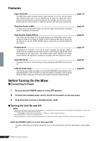
sure that the channel faders, ST master fader, AUX1/2 faders, ST SUB OUT control are all the way down. Push the POWER switch in to turn the power ON. The power lamp lights up to indicate that power is on. To turn the power off, push the switch again, so that it pops out. 6 EMX5014C Owner's Manual - Yamaha EMX5014C | Owner's Manual - Page 7
Mixer Basics Quick Guide Getting Sound to the Speakers We begin by connecting up two speakers and generating some stereo output. Note that operations and procedures will vary somewhat according to the input devices you are using. 1 1 Connect up the speakers and your input devices (microphones, - Yamaha EMX5014C | Owner's Manual - Page 8
and to all other devices having internal amplifiers. We also recommend that you turn all output controls (Channel faders, ST Master fader, etc.) to minimum settings before operating the switch, to avoid risk of loud noises that could cause hearing loss or device damage. 8 EMX5014C Owner's Manual - Yamaha EMX5014C | Owner's Manual - Page 9
you can monitor these signals through the headphones. Turn the ON switch on. 9 Set the ST Master fader to the "0" position. Mixer Basics Quick Guide 10 Adjust the channel faders on all occupied channels. Adjust the faders while listening to the output from the speakers. NOTE • To use the LEVEL - Yamaha EMX5014C | Owner's Manual - Page 10
the effect depth for each channel. 5 Use the EFFECT RTN fader to adjust the overall effect depth. Note that you can use the PARAMETER knob to adjust the characteristic sound of the selected effect. If you have selected a reverb effect, the knob adjusts the reverb time. 10 EMX5014C Owner's Manual - Yamaha EMX5014C | Owner's Manual - Page 11
lyrics are easier to hear. 1 1 Adjust the COMP knobs on the relevant channels. Turn the knob clockwise to increase the compression. Avoid setting the value too high, as too much compression may result in howling. For more information about the compressors, see page 18. EMX5014C Owner's Manual 11 - Yamaha EMX5014C | Owner's Manual - Page 12
. If the corresponding circuitry is designed properly, however, XLR-type connectors will also handle unbalanced signals with no problem. Microphone cables usually have this type of connector, as do the inputs and outputs of most professional audio gear. Male Female 12 EMX5014C Owner's Manual - Yamaha EMX5014C | Owner's Manual - Page 13
. The reason for this is that the output signal from most microphones is very small, so even a tiny amount of noise will be relatively large, and will be amplified to an alarming degree in the mixer's high-gain head amplifier. To summarize Microphones: Use balanced lines. Short line-level runs - Yamaha EMX5014C | Owner's Manual - Page 14
Balanced owner's manual. + 20 dBu 0 dBu 0.775 V -20 dBu Most professional mixers, power amplifiers, and other types of equipment have inputs and outputs with a nominal level of +4 dBu. The inputs and outputs on home-use drum beat might produce a level as high as 0 dBu. 14 EMX5014C Owner's Manual - Yamaha EMX5014C | Owner's Manual - Page 15
vocal channel up to nominal first (if your level setup drum). They should almost sound like a single instrument-with the kick supplying the punch and the bass supplying the pitch. Once again, there are no rules, but these are concepts that have been proven to work well. EMX5014C Owner's Manual - Yamaha EMX5014C | Owner's Manual - Page 16
biggest problems with too much boost is that it adds gain to the signal, increasing noise and potentially overloading the subsequent circuitry. Signal Level (dB) LOW Boost MID Boost LOW Flat MID Flat HIGH Boost HIGH Flat LOW Cut MID Cut Frequency (Hz) HIGH Cut 16 EMX5014C Owner's Manual - Yamaha EMX5014C | Owner's Manual - Page 17
uses longer delay times than chorus, whereas chorus generally uses a more complex delay structure. Chorus is most often used to thicken the sound of an instrument, while flanging is usually used as an outright "special effect" to produce otherworldly sonic swoops. EMX5014C Owner's Manual 17 - Yamaha EMX5014C | Owner's Manual - Page 18
technique is being used to drive the message? That's where the focus of your mix should be. You're using a high-tech tool to do the mixing, but the mix itself is as much art as the music. Approach it that way and your mixes will become a vital part of the music. 18 EMX5014C Owner's Manual - Yamaha EMX5014C | Owner's Manual - Page 19
accept stereo inputs. Use these to connect up stereo output devices, such as stereo synthesizers and CD players. LINE jacks: Unbalanced stereo inputs. On channel pairs 7/8 and 13/14 these are phone jacks; on channel pairs 11/12 and 13/14 they are RCA pin jacks. MIC jack: XLR balanced stereo mic - Yamaha EMX5014C | Owner's Manual - Page 20
this HPF to the line inputs of stereo input channels.) 7 COMP knob (Channels 1 to 6) This knob adjusts the level of compression applied to the channel. As the knob is turned to the right, the mixer automatically raises the compression ratio while adjusting the output gain accordingly. The result is - Yamaha EMX5014C | Owner's Manual - Page 21
are OFF, the channel output is not fed to the PHONES jack. H Channel Fader Adjusts the signal's output level. Use these faders to adjust the volume balance among the various channels. NOTE To reduce noise, set the fader sliders for unused channels all the way down. EMX5014C Owner's Manual 21 - Yamaha EMX5014C | Owner's Manual - Page 22
O 22 EMX5014C Owner's Manual I SEND Jack • EFF This unbalanced phone output jack outputs the signal from the EFFECT bus. You use this jack, for example, to connect to an external effector. You can then return the signal by connecting the external effector to any of the LINE jacks on channel pairs - Yamaha EMX5014C | Owner's Manual - Page 23
is ON, the channel's output is mixed into the monitor signal to the PHONES jack. If both switches are OFF, the channel output is not fed to the PHONES jack. O EFFECT RTN Fader Adjusts the level of the effected sound into the Stereo bus. Reference Front & Rear Panels EMX5014C Owner's Manual 23 - Yamaha EMX5014C | Owner's Manual - Page 24
] P REC OUT Jacks These RCA pin-type unbalanced output jacks can be used to send the main stereo signal to an external DAT P recorder or cassette recorder. The jacks output the ste- reo signal pre adjustment by the ST until the lamps flash only briefly or not at all. 24 EMX5014C Owner's Manual - Yamaha EMX5014C | Owner's Manual - Page 25
frequency balance may vary according to the speakers you are using. \ PHANTOM Switch and Indicator This switch toggles phantom power on and off. The indicator lights up when the setting is on. If you set the switch on, the mixer supplies power to the XLR mic input jacks on all channels (the INPUT - Yamaha EMX5014C | Owner's Manual - Page 26
mix to be monitored at the PHONES jack. If the channel's PFL or AFL switch is ON, the channel's output is mixed into the monitor signal to the output from the ST g SUB OUT jacks. • The signal to the SPEAKERS jacks is determined by the setting of the POWER AMP switch Z. 26 EMX5014C Owner's Manual - Yamaha EMX5014C | Owner's Manual - Page 27
B2: Phone output jacks. i POWER Switch This switch turns the EMX power ON and OFF. The POWER indicator U lights up when this switch is on. Before turning the power ON or OFF using this ground screw. Correct grounding will effectively eliminate hum noise and interference. EMX5014C Owner's Manual 27 - Yamaha EMX5014C | Owner's Manual - Page 28
by 2-channel connection, use speakers with impedance of 4 ohms to 8 ohms. 4Ω - 8Ω 4Ω - 8Ω 2-channel parallel connection When connecting speakers in parallel as shown below, use speakers with impedance of 8 ohms to 16 ohms. 8Ω - 16Ω 8Ω - 16Ω 8Ω - 16Ω 8Ω - 16Ω 28 EMX5014C Owner's Manual - Yamaha EMX5014C | Owner's Manual - Page 29
, and screw them in using the screws (silver) included in the RK5014. Do not use the screws (black) you just removed from the EMX unit. 3 Mount the unit into the rack, and fasten it into place. Do not install the mixer near power amps or other heat-generating devices. EMX5014C Owner's Manual 29 - Yamaha EMX5014C | Owner's Manual - Page 30
Monitor Speakers ST SUB OUT, or AUX 1/2 jacks, and then connecting speakers to the power amp. CD Player Recorder Foot Switch (YAMAHA FC5) Headphones Microphones Microphones Effect processor (exciter) Drums Rear Panel 30 EMX5014C Owner's Manual Effect processor (delay) Power Amp Power - Yamaha EMX5014C | Owner's Manual - Page 31
the AUX1 and AUX2 faders. ❑ If you want to send the monitor signal to SPEAKERS A jack, set the POWER AMP switch to the AUX1/MONO position. (Note that in this case the A jack will output the monitor signal, and the B jack will output a mix of the stereo L and R signals.) EMX5014C Owner's Manual 31 - Yamaha EMX5014C | Owner's Manual - Page 32
-fault: power supply shutdown/manual reset Thermal/heatsink temp >= 90˚C: output mute/auto reset Vl limiter /RL = 1 % , Indicator × 2 Thermal/heatsink temp >= 100˚C: power supply shutdown/manual reset Dual variable-speed fan Power Consumption AC Cord Length Dimensions - Yamaha EMX5014C | Owner's Manual - Page 33
are balanced. (Tip=HOT, Ring=COLD, Sleeve=GND ) *5 Phone Jacks are unbalanced. ■ Output Characteristics Output Terminals ST OUT [L, R] ST SUB OUT [L, R] AUX SEND 1, 2 EFFECT SEND CH INSERT OUT 1-6 REC OUT [L, R] PHONES [L, R] Actual Source Impedance For Use with Nominal Output Level Nominal - Yamaha EMX5014C | Owner's Manual - Page 34
Dimensional Diagrams Reference Specifications 444 (440 excluding screw heads) 155 145 6 8 485 493 Unit: mm EMX5014C Owner's Manual 34 - Yamaha EMX5014C | Owner's Manual - Page 35
EMX5014C Owner's Manual 35 CH INPUT A CH1-6 [-60dBu~-16dBu] [-34dBu~+10dBu] B INSERT I/O [0dBu] ST CH MIC 1 B:R/MONO/AUX2 2 1 REC OUT [-10dBV] Clip Level Clip Level SPEAKER OUT (+35.2dBu) MAXIMUM OUTPUT POWER[500w4ohms] [125w/4ohms] (+29.2dBu) ST OUT, ST SUB OUT [+4dBu] AUX SEND,EFFECT SEND - Yamaha EMX5014C | Owner's Manual - Page 36
Bldg. 158-9 Samsung-Dong, Kangnam-Gu, Seoul, Korea Tel: 080-004-0022 MALAYSIA Yamaha Music Malaysia, Sdn., Bhd. Lot 8, Jalan Perbandaran, 47301 Kelana Jaya, Petaling Jaya, Selangor, Malaysia Tel: 3-78030900 SINGAPORE Yamaha Music Asia Pte., Ltd. #03-11 A-Z Building 140 Paya Lebor Road, Singapore - Yamaha EMX5014C | Owner's Manual - Page 37
Yamaha Pro Audio global web site http://www.yamahaproaudio.com/ Yamaha Manual Library http://www.yamaha.co.jp/manual/ U.R.G., Pro Audio & Digital Musical Instrument Division, Yamaha Corporation © 2005 Yamaha Corporation WG13770 702CRAPx.x-04C0 Printed in China
-
 1
1 -
 2
2 -
 3
3 -
 4
4 -
 5
5 -
 6
6 -
 7
7 -
8
-
9
-
10
-
11
-
12
-
13
-
14
-
15
-
16
-
17
-
18
-
19
-
20
-
21
-
22
-
23
-
24
-
25
-
26
-
27
-
28
-
29
-
30
-
31
-
32
-
33
-
34
-
35
-
36
-
37
 |
 |
POWERED MIXER
POWERED MIXER
Owner’s Manual
Owner’s Manual
EN
Making the Most of Your Mixer
Pages 12 to 18
Quick Guide
Pages 7 to 11