Yamaha EMX5014C Owner's Manual - Page 26
PFL Pre-Fader Listen Switch, AFL After-Fader Listen Switches, AUX1 and AUX2 Faders, ST Master Fader - monitor
 |
UPC - 086792838274
View all Yamaha EMX5014C manuals
Add to My Manuals
Save this manual to your list of manuals |
Page 26 highlights
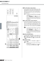
Reference Front & Rear Panels f d PFL (Pre-Fader Listen) Switch Set this switch on if you want to monitor the pre-fade of the signal that is being output at the ST OUT or ST SUB OUT jacks. If the switch is on, the signal (prior to adjustment by the ST master fader and ST SUB control) is fed to the PFL bus so that it can be monitored at the PHONES jack. NOTE • The signal level into the PFL bus is not affected by the settings of the ST master fader and ST SUB OUT Control. • The PFL (G, N, d) and AFL e switches select the mix to be monitored at the PHONES jack. If the channel's PFL or AFL switch is ON, the channel's output is mixed into the monitor signal to the PHONES jack. e AFL (After-Fader Listen) Switches Set this relevant switch on if you want to monitor the post-fade of the signal that is being output at the ST OUT or the SEND AUX1 or SEND AUX2 jack. If the switch is on, the signal (following adjustment by the ST master fader or AUX1 or AUX2 fader) is fed to the AFL bus so that it can be monitored at the PHONES jack. NOTE • The signal levels into the AFL bus are not affected by the settings of the ST master fader or the AUX1/2 fader settings. • The PFL (G, N, d) and AFL e switches select the mix to be monitored at the PHONES jack. If the channel's PFL or AFL switch is ON, the channel's output is mixed into the monitor signal to the PHONES jack. f AUX1 and AUX2 Faders The AUX1 fader adjusts the level of the output from the SPEAKERS A jacks h or the SEND AUX1 jack I. The AUX2 fader adjusts the level of the output from the SPEAKERS B jacks h or the SEND AUX2 d jack I. e g ST Master Fader Adjusts the level to the SPEAKERS jacks h or ST OUT jacks S. NOTE • Does not affect the level of the output from the ST g SUB OUT jacks. • The signal to the SPEAKERS jacks is determined by the setting of the POWER AMP switch Z. 26 EMX5014C Owner's Manual
-
 1
1 -
2
-
3
-
4
-
5
-
6
-
7
-
8
-
9
-
10
-
11
-
12
-
13
-
14
-
15
-
16
-
17
-
18
-
19
-
20
-
 21
21 -
 22
22 -
 23
23 -
 24
24 -
 25
25 -
 26
26 -
 27
27 -
 28
28 -
 29
29 -
 30
30 -
 31
31 -
32
-
33
-
34
-
35
-
36
-
37
 |
 |
