Yamaha KX-W392 Owner's Manual - Page 4
Connections, Notes On This Manual, Example: Kx-w592 - cassette deck
 |
View all Yamaha KX-W392 manuals
Add to My Manuals
Save this manual to your list of manuals |
Page 4 highlights
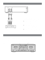
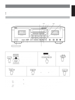
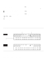
LINE IN-LINE OUT REC PLAY 4 3 L R CONNECTIONS To an AC outlet REC OUT TAPE PB L R Amplifier or receiver REAR PANEL CONNECTIONS Make sure that power to both the deck and your amplifier/ receiver is turned off before making any connections. ÷ The White plug on the paired connecting cables corresponds to the Left channel and the Red plug corresponds to the Right channel. Make sure that the left and right channel connections are properly made, and that the plugs are inserted firmly. ÷ The LINE OUT/PLAY jacks on the deck should be connected to the Tape PB (Playback/Input) jacks on your amplifier/receiver, and the LINE IN/REC jacks on the deck should be connected to the Rec Out (Recording/Output) jacks on your amplifier/receiver. ÷ Connect the power cord to an AC wall outlet or to an AC outlet on the rear panel of your amplifier/receiver (if provided). NOTES ON THIS MANUAL In this manual, the main operation buttons of the front panel are indicated based on DECK B when the operation is common to both DECKs A and B. Since the locations of the buttons of DECK B and DECK A are the same, you can easily find the desired button even when operating DECK A. This manual covers three models. In most cases, however, only model KX-W592 is shown in the example illustrations. Example: KX-W592 Main operation buttons of DECK A Main operation buttons of DECK B NATURAL SOUND STEREO DOUBLE CASSETTE DECK KX-W592 DIRECTION RESET RESET DIRECTION Cassette Stabilizer RECORD/PLAYBACK DECK A ! PLAY ⁄ ! PLAY ⁄ MUTE/SEARCH STOP REC/PAUSE MUTE/SEARCH STOP REC/PAUSE POWER MODE O / p / ∏ / RELAY DOLBY NR OFF/ B/ C EJECT DUBBING A # B NORMAL HIGH DSS DSS MODE EFFECT EJECT Cassette Stabilizer RECORD/PLAYBACK DECK B PLAY TRIM 0 -+ BALANCE REC LEVEL 21 0 12 34 5 67 3 3 2 8 4 4 1 9 L5 5R 0 10 PHONES 4
-
 1
1 -
 2
2 -
 3
3 -
 4
4 -
 5
5 -
 6
6 -
 7
7 -
 8
8 -
 9
9 -
 10
10 -
11
-
12
-
13
-
14
-
15
-
16
-
17
-
18
-
19
-
20
 |
 |
