Yamaha MCR-E600 MCR-E600 Owners manual Receiver only - Page 6
Connecting the speakers and antennas
 |
UPC - 027108104270
View all Yamaha MCR-E600 manuals
Add to My Manuals
Save this manual to your list of manuals |
Page 6 highlights
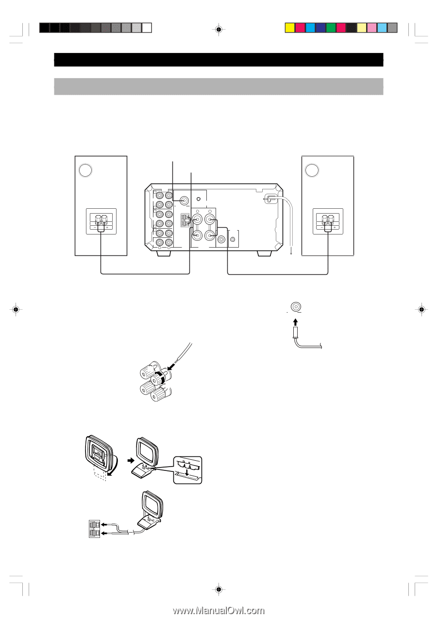
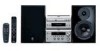
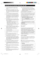
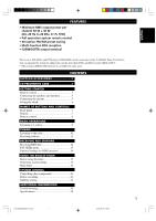
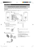
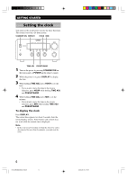
GETTING STARTED Connecting the speakers and antennas Never plug the AC power cord to the wall outlet until all connections are completed. Follow the steps as shown below to connect the system using the supplied cords and accessories. Be sure all connections are made correctly, that is to say L (left) to L, R (right) to R, "+" to "+" and "-" to "-". Right speaker 3 FM antenna 2 AM loop antenna Left speaker C IN MD OUT D A IN TAPE OUT B E IN DVD IN AUX R FM ANT 75Ω UNBAL. GND AM ANT DVD SYSTEM CONNECTOR R L + - SUBWOOFER SYSTEM OUT CONNECTOR 6Ω MIN./SPEAKER L TUNER SPEAKERS 1 4 To wall outlet 1 Connect the Speakers. 1 Unscrew the knob. 2 Remove approx. 10 mm (4") of insulation from each of the speaker wires and insert the bare wire into the terminal. 3 Tighten the knob to secure the wire. 3 Connect the FM Antenna. FM ANT 75 Ω UNBAL Red: positive(+) Black: negative(-) 2 1 3 2 Connect the AM Antenna. Set up the AM loop antenna, then connect it. 4 Connect the AC power cord to a wall outlet. Notes • Use external FM/AM antennas if you need better reception. Consult your dealer. • The AM loop antenna should be placed apart from the main unit. The antenna may be hung on a wall. To connect the subwoofer (optional) You can reinforce the bass frequencies by adding a subwoofer (optional). Connect the SUBWOOFER OUT terminal of the unit to the INPUT terminal of the subwoofer. GND AM ANT 4 0104CRXE400(M).03-08.E 4 2004.06.15, 19:06
-
 1
1 -
 2
2 -
 3
3 -
 4
4 -
 5
5 -
 6
6 -
 7
7 -
 8
8 -
 9
9 -
 10
10 -
 11
11 -
 12
12 -
13
-
14
-
15
-
16
-
17
-
18
-
19
-
20
-
21
-
22
-
23
-
24
-
25
-
26
 |
 |