Yamaha MCX-10 MCX-10 OWNERS MANUAL - Page 3
Component, Names, Their, Functions
 |
View all Yamaha MCX-10 manuals
Add to My Manuals
Save this manual to your list of manuals |
Page 3 highlights
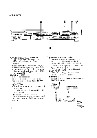
COMPONENT NAMES AND THEIR FUNCTIONS • FRONT PANEL NATURAL BOUND MASTER NE CONTROLLER NICX-1O ZONE I *moor) c6 I ZONE 2 ZONE 3 ifr0YMErri ON ZONE ON ZONE 6 POWER Switch and Indicator When you press this switch, the indicator goes on and the MCX-10 is turned on. It is turned off and the indicator goes off when you push the switch the second time. When it is turned off, it does not respond to the Remote-control Transmitter (RCX-10) or to the ON/STANDBY switch of the Zone Control/Sensor (WCX-10). Zone Control Switch and Indicators Each zone control switch lets you set the unit in the ON, STANDBY or OFF position. Each time you push the right-hand side of the switch, the activated indicator changes from OFF to STANDBY and to ON in this order. Pushing the left-hand side of the switch changes the activated indicator from ON to STANDBY and then to OFF in this order. OFF position: The MCX-10 does not respond to signals from the remote controller and no sounds are heard from the speakers. STANDBY position: The Zone Control/Sensor (WCX-10) is in the standby state. It is turned on as soon as the Zone Control switch of the WCX-10 or the ROOM ON/ OFF switch of the remote controller is pressed, and it begins to control individual audio devices in the selected zone. ON position: The selected audio equipment is ready for control and the speakers are turned on. * The above mode selections are linked with the indicators on individual Zone Control/Sensors (WCX-10). * All indicators (OFF-STANDBY -ON) remain off for zones to which no WCX-10 is connected. 3
-
 1
1 -
 2
2 -
 3
3 -
 4
4 -
 5
5 -
 6
6
 |
 |
