Yamaha MCX-10 MCX-10 OWNERS MANUAL - Page 4
Yamaha MCX-10 Manual
 |
View all Yamaha MCX-10 manuals
Add to My Manuals
Save this manual to your list of manuals |
Page 4 highlights
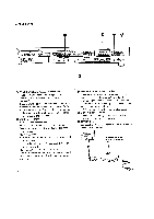
REAR PANEL 0 12V ANZN7ANA IIra an © © ©O Hp6 MeV a YMTHA OINK:WON MNIE ZONE 4 MON.S , ma CAO ZONE CONTROL/6B160.8 ZONE 2 © O O MOM INDEPENDENT ZONE ZONE 1 .4. © ©© FROM ALL ZONE 0 M MitnIMM .Y L4.;,€ .0 © OF rm.. COW..ma.P•Or le OF I ITINECC oPENA C. le SWUM TO 'VMAlAy Nor co..o. r c (-5INTERFERENGE.ANA. MT), colICA MST AccEro ANY INTERATINICE MOAT. I.E THAT NAY GAM 14402.B3 ofANATIoN O €) ZONE CONTROL/SENSORS Terminals These terminals supply control signals and electricity to each Zone Control/Sensor (WCX-10). These terminals connect to terminals of the same names on individual Zone Control/Sensors (WCX10). Each group (1 to 5) of terminals corresponds to the zone control switch indicator of the same zone number in the front panel. • EMITTER Terminals FROM INDEPENDENT ZONE: Remote-control signals in a zone are supplied from these terminals to the emitter of the same zone number. FROM ALL ZONE: All remote-control signals in all zones are supplied to the emitters. * Up to six emitters may be connected in series to each terminal. FROM SELECTED ZONE selection switch: Only remote-control signals for the zones selected by this switch are supplied to the corresponding emitters. le Powered Emitter Output Terminals These terminals provide the same signals as those from right-hand FROM SELECTED ZONE terminal. Terminals have screw-on type fasteners so that wires of any type may be connected. They also provide +.9V electricity. * NC (no connection) terminal is left unused. • MCX-10 LINK Terminal A second MCX-10 may be connected to this terminals to control up to ten zones. • 12V DC Jack Connect the PA-1210 External AC Power Adaptor (provided) to this jack. 5 PA-1210 AC Power Adaptor (designed exclusively for MCX-10) 4
-
 1
1 -
 2
2 -
 3
3 -
 4
4 -
 5
5 -
 6
6
 |
 |
