Yamaha YDP-165 YDP-165_YDP-145_YDP-S55_YDP-S35_Owners Manual - Page 34
YDP-165, YDP-145 Assembly, Align the side boards with each end, of pedal box, and lightly tighten
 |
View all Yamaha YDP-165 manuals
Add to My Manuals
Save this manual to your list of manuals |
Page 34 highlights
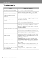
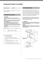
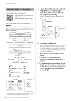
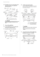
Keyboard Stand Assembly YDP-165, YDP-145 Assembly You can watch a video of the assembly. Scan the QR code at left or access the website below. https://4wrd.it/ydp_assembly_video1 Check if you have all of the items indicated below. NOTICE Make sure to place the main unit on the polystyrene foam pads that have been removed from the packages. Position the pads so that they will not contact the speaker covers on the bottom of the main unit. 1. Align the side boards with each end of pedal box, and lightly tighten with flat head screws (6 × 20 mm) for temporary fastening These screws will be tightened securely later in step 3. Side board (R) Pedal box Side board (L) Main unit × 4 Flat head screws (6 × 20 mm) Speaker cover Polystyrene foam pads Speaker cover Back board Pedal box Cord holder Side board (L) Side board (R) × 4 Flat head screws (6 × 20 mm) × 4 Caps × 2 Thin screws (4 × 12 mm) × 4 Thick screws (6 × 16 mm) × 4 Tapping screws (4 × 20 mm) YDP-165 YDP-145 AC adaptor Power cord Headphone hanger set Headphone hanger × 2 Screws (4 × 10 mm) AC adaptor * The adaptor may not be included, or may look different from the illustration above, depending on your particular area. 34 YDP-165, YDP-145, YDP-S55, YDP-S35 Owner's Manual 2. Attach the back board. Depending on the model, the surface color of one side of the back board may be different from the other side. In this case, position the back board so that the side facing the front (pedal side) matches the color of the main unit. 2-1 Place the back board on each foot of side boards. 2-2 Attach the top of the back board by temporarily fastening the thin screws (4 × 12 mm). 2-3 While pushing on the lower part of the side boards from the outside, secure the bottom ends of the back board using tapping screws (4 × 20 mm) in the order from outside to inside (1 → 2).
-
 1
1 -
2
-
3
-
4
-
5
-
6
-
7
-
8
-
9
-
10
-
11
-
12
-
13
-
14
-
15
-
16
-
17
-
18
-
19
-
20
-
21
-
22
-
23
-
24
-
25
-
26
-
27
-
28
-
 29
29 -
 30
30 -
 31
31 -
 32
32 -
 33
33 -
 34
34 -
 35
35 -
 36
36 -
 37
37 -
 38
38 -
 39
39 -
40
-
41
-
42
-
43
-
44
-
45
-
46
-
47
-
48
 |
 |
