Yamaha YDP-165 YDP-165_YDP-145_YDP-S55_YDP-S35_Owners Manual - Page 39
Connect the pedal cord plug and the, Rotate the adjuster until it presses
 |
View all Yamaha YDP-165 manuals
Add to My Manuals
Save this manual to your list of manuals |
Page 39 highlights
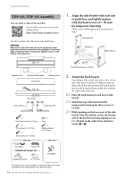
Keyboard Stand Assembly 6. (YDP-S55 only) With the non-felt side of the front board facing the front (pedal side), fix it with thin screws (4 × 12 mm). Install so that the gap between the side boards (L) and (R) is equal on both sides. × 2 Thin screws (4 × 12 mm) Main unit NOTICE If it is not plugged in firmly, it may cause the pedals to not work. 7-2 Wind the cord holder around pedal cord to hold it. The cord holder is attached to the side board (L). 7-3 (YDP-S55 only) Connect the power cord to the AC adaptor. Side board (L) Front board Back board Front board back side Felt Side board (R) 7-4 Insert the DC plug into the DC IN jack. 7. Connect the pedal cord plug and the power plug. 7-1 TO PEDAL 8. Rotate the adjuster until it presses in firm contact with the floor surface. Make sure that the pedal box does not rattle or give way when you step on the pedals. 7-4 DC IN 7-2 Cord holder 7-1 Insert the pedal cord plug to the [TO PEDAL] jack from the rear. Insert the plug until the metal part disappears from view. Metal part To press against the floor To separate from the floor 39 YDP-165, YDP-145, YDP-S55, YDP-S35 Owner's Manual
-
 1
1 -
2
-
3
-
4
-
5
-
6
-
7
-
8
-
9
-
10
-
11
-
12
-
13
-
14
-
15
-
16
-
17
-
18
-
19
-
20
-
21
-
22
-
23
-
24
-
25
-
26
-
27
-
28
-
29
-
30
-
31
-
32
-
33
-
 34
34 -
 35
35 -
 36
36 -
 37
37 -
 38
38 -
 39
39 -
 40
40 -
 41
41 -
 42
42 -
 43
43 -
 44
44 -
45
-
46
-
47
-
48
 |
 |
