Yamaha YPG-535 Owner's Manual - Page 10
Setting Up, Keyboard Stand Assembly - owner s manual
 |
View all Yamaha YPG-535 manuals
Add to My Manuals
Save this manual to your list of manuals |
Page 10 highlights
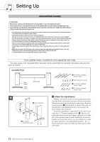
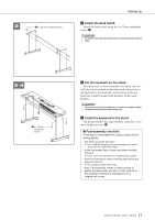
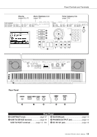
Setting Up Keyboard Stand Assembly CAUTION Read these cautions carefully before you assemble or use the keyboard stand. These cautions are to promote safe use of the stand and to prevent injury and damage from occurring to you and others. By following these cautions carefully, your keyboard stand will provide you with safe and prolonged use. • Be careful not to confuse parts, and be sure to install all parts in the correct direction. Please assemble in accordance with the sequence given below. • Assembly should be carried out by at least two persons. • Be sure to use the correct screw size, as indicated below. Use of incorrect screws can cause damage. • Use the stand after assembly is complete. An uncompleted stand may overturn or the keyboard may drop. • Always place the stand on a flat, stable surface. Placing the stand on uneven surfaces may cause it to become unstable or overturn, the keyboard to drop, or injury. • Do not use the stand for anything other than its designed purpose. Placing other objects on the stand may result in the object dropping or the stand overturning. • Do not apply excessive force to the keyboard as it may cause the stand to overturn or the keyboard to drop. • Make sure the stand is sturdy and safe, and all screws have been tight and firm before use. If not, the stand may overturn, the keyboard may drop, or may result in injury to the user. • To disassemble, reverse the assembly sequence given below. Have a phillips-head (+) screwdriver of the appropriate size ready. The parts shown in the "Assembly Parts" illustration will be used. Follow the assembly instructions and select the parts as needed. Assembly Parts Side boards Stand bases Back board q 6 x 70 mm roundhead screws (4 pcs.) w Joint connectors (4 pcs.) e 6 x 30 mm roundhead screws (4 pcs.) r 5 x 16 mm roundhead screws (4 pcs.) 1 z Attach the stand bases. Making sure that the boards are facing the proper direc- tion (the holes for the joint connectors should face inside). w Joint connectors The left and right side boards are the same shape. Insert the joint connectors w into the holes as shown. The joint con- nectors have been installed properly if you can see the screw head on the connector. Attach the stand bases to the bottom of the side boards, using the 6 x 70 mm roundhead screws q. The left and right stand bases are the same shape, and there is no differ- ence between their front-to-back orientation. If you have trouble screwing in the screws, use a screwdriver to rotate q 6 x 70 mm roundhead screws the joint connectors to the appropriate position-the → mark on the joint connectors indicates the location of the screw hole. 10 DGX-530/YPG-535 Owner's Manual
-
 1
1 -
2
-
3
-
4
-
 5
5 -
 6
6 -
 7
7 -
 8
8 -
 9
9 -
 10
10 -
 11
11 -
 12
12 -
 13
13 -
 14
14 -
 15
15 -
16
-
17
-
18
-
19
-
20
-
21
-
22
-
23
-
24
-
25
-
26
-
27
-
28
-
29
-
30
-
31
-
32
-
33
-
34
-
35
-
36
-
37
-
38
-
39
-
40
-
41
-
42
-
43
-
44
-
45
-
46
-
47
-
48
-
49
-
50
-
51
-
52
-
53
-
54
-
55
-
56
-
57
-
58
-
59
-
60
-
61
-
62
-
63
-
64
-
65
-
66
-
67
-
68
-
69
-
70
-
71
-
72
-
73
-
74
-
75
-
76
-
77
-
78
-
79
-
80
-
81
-
82
-
83
-
84
-
85
-
86
-
87
-
88
-
89
-
90
-
91
-
92
-
93
-
94
-
95
-
96
-
97
-
98
-
99
-
100
-
101
-
102
-
103
-
104
-
105
-
106
-
107
-
108
-
109
-
110
-
111
-
112
-
113
-
114
-
115
-
116
-
117
-
118
-
119
-
120
-
121
-
122
-
123
-
124
-
125
-
126
-
127
-
128
-
129
-
130
-
131
-
132
-
133
-
134
-
135
-
136
-
137
-
138
-
139
-
140
-
141
-
142
-
143
-
144
 |
 |