Yamaha YSP-3050 Owner's Manual - Page 24
Case 3: Connecting other connection methods, Video
 |
UPC - 027108930282
View all Yamaha YSP-3050 manuals
Add to My Manuals
Save this manual to your list of manuals |
Page 24 highlights
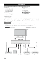
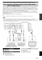
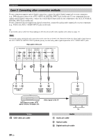
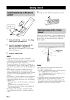
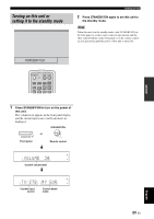
Connections Case 3: Connecting other connection methods If your component supports optical digital connections, connect the optical digital output jack on your component (e.g., DVD player/recorder) to the AUX 1 OPTICAL DIGITAL INPUT jack on this unit. If your component does not support optical digital connections, connect the coaxial digital output jack on your component to the AUX 2 COAXIAL DIGITAL INPUT jack on this unit. If your component does not support any digital connections, connect the analog audio output jacks on your component (e.g., VCR) to the AUX 1 AUDIO INPUT jacks on this unit. y To prevent the optical cable from being unplugged, affix the optical cable in the supplied cable clamp (see page 17). Note If you make analog and digital audio connections at the same time as shown in the illustration below, the digital audio signals input at the AUX 1 OPTICAL DIGITAL INPUT jack take priority over the analog audio signals input at the AUX 1 AUDIO INPUT jacks. Rear panel of this unit AUDIO INPUT OUT VIDEO VIDEO INPUT COMPONENT AUX 1 TV/STB SUBWOOFER STB DVD DIGITAL INPUT AUX 2 DVD COAXIAL OPTICAL AUX 1 TV/STB 1 3 2 R L Analog audio output Coaxial digital output Optical digital output Video input DVD player/recorder, VCR, game console, CD player, etc. Video OSD video pin cable Video signal to the TV TV Audio Audio pin cable Optical cable Digital audio pin cable 20 En
-
 1
1 -
2
-
3
-
4
-
5
-
6
-
7
-
8
-
9
-
10
-
11
-
12
-
13
-
14
-
15
-
16
-
17
-
18
-
 19
19 -
 20
20 -
 21
21 -
 22
22 -
 23
23 -
 24
24 -
 25
25 -
 26
26 -
 27
27 -
 28
28 -
 29
29 -
30
-
31
-
32
-
33
-
34
-
35
-
36
-
37
-
38
-
39
-
40
-
41
-
42
-
43
-
44
-
45
-
46
-
47
-
48
-
49
-
50
-
51
-
52
-
53
-
54
-
55
-
56
-
57
-
58
-
59
-
60
-
61
-
62
-
63
-
64
-
65
-
66
-
67
-
68
-
69
-
70
-
71
-
72
-
73
-
74
-
75
-
76
-
77
-
78
-
79
-
80
-
81
-
82
-
83
-
84
-
85
-
86
-
87
-
88
-
89
-
90
-
91
-
92
-
93
-
94
-
95
-
96
-
97
-
98
-
99
-
100
-
101
-
102
-
103
-
104
-
105
-
106
-
107
-
108
-
109
-
110
-
111
-
112
-
113
-
114
-
115
-
116
-
117
-
118
 |
 |
