Yamaha YST-SW325 Owner's Manual - Page 14
Auto Standby High/low/off, Warning
 |
UPC - 027108923352
View all Yamaha YST-SW325 manuals
Add to My Manuals
Save this manual to your list of manuals |
Page 14 highlights
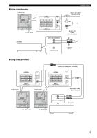
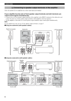
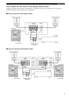
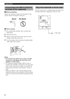
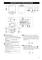
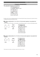
CONTROLS AND THEIR FUNCTIONS 5 HIGH CUT control Adjusts the high frequency cut off point. Frequencies higher than the frequency selected by this control are all cut off (and no output). * One graduation of this control represents 10 Hz. 6 VOLUME control Adjusts the volume level. Turn the control clockwise to increase the volume, and counterclockwise to decrease the volume. 7 POWER switch Normally, set this switch to the ON position to use the subwoofer. In this state, you can turn on the subwoofer or turn the subwoofer into the standby mode by pressing the STANDBY/ON button. Set this switch to the OFF position to completely cut off the subwoofer's power supply from the AC line. 8 AUTO STANDBY (HIGH/LOW/OFF) switch This switch is originally set to the OFF position. By setting this switch to the HIGH or LOW position, the subwoofer's AUTO STANDBY function operates as described on page 11. If you do not need this function, leave this switch in the OFF position. * Make sure to change the setting of this switch only when the subwoofer is set in the standby mode by pressing the STANDBY/ON button. 9 OUTPUT (TO SPEAKERS) terminals Can be used for connecting to the front speakers. Signals from the INPUT1 terminals are sent to these terminals. (Refer to page 7 of "CONNECTIONS" for details.) 0 INPUT1 (FROM AMPLIFIER) terminals Used to connect the subwoofer with the speaker terminals of the amplifier. (Refer to pages 6 and 7 of "CONNECTIONS" for details.) A INPUT2 terminals Used to input line level signals from the amplifier. (Refer to pages 4 and 5 of "CONNECTIONS" for details.) B PHASE switch Normally this switch is to be set to the REV (reverse) position. However, according to your speaker systems or the listening condition, there may be a case when better sound quality is obtained by setting this switch to the NORM (normal) position. Select the better position by monitoring the sound. C VOLTAGE SELECTOR switch (Asia and General models only) If the preset setting of the switch is incorrect, set the switch to the proper voltage (110-120/220-240V) of your area. Consult your dealer if you are unsure of the correct setting. WARNING Be sure to unplug the subwoofer before setting the VOLTAGE SELECTOR switch correctly. Note When both @INPUT1 and AINPUT2 terminals of the subwoofer are connected with the amplifier, you may hear a mixed sound due to the effect of the subwoofer receiving the input signals from both the terminals. If this happens, connect the amplifier only to either the @INPUT1 or AINPUT2 terminal. 10
-
 1
1 -
2
-
3
-
4
-
5
-
6
-
7
-
8
-
 9
9 -
 10
10 -
 11
11 -
 12
12 -
 13
13 -
 14
14 -
 15
15 -
 16
16 -
 17
17 -
 18
18 -
 19
19 -
20
 |
 |
