Zenith DTT901 Operation Guide - Page 4
Front, Connection, Panel, Overview - remote control
 |
View all Zenith DTT901 manuals
Add to My Manuals
Save this manual to your list of manuals |
Page 4 highlights
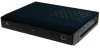
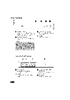
Front Panel _= o .= [] [] [] [] h'! POWER indicator Lights up red (standby mode) or blue (active mode). This indicator will blink when remote signal is received. FJI Remote Control Sensor Receives signals from the Remote Control. t_ VIA (Channel Down/Up) Scans up or down through memorized channels. [] POWER Turns the unit on or off. Connection Panel Overview [] [] [] [] n From Antenna Connect to digital signal source; over-the-air antenna. m To TV (RF) Connect to a TV with RF coaxial inputs. VIDEO and AUDIO OUTPUT (Left/Right) Connect to a TV/Monitor with Video and audio inputs. [] AC Power Cord Plug into the power source.
-
 1
1 -
 2
2 -
 3
3 -
 4
4 -
 5
5 -
 6
6 -
 7
7 -
 8
8 -
 9
9 -
 10
10 -
11
-
12
-
13
-
14
-
15
-
16
-
17
-
18
-
19
-
20
-
21
-
22
-
23
-
24
-
25
-
26
-
27
-
28
-
29
-
30
-
31
-
32
-
33
-
34
-
35
-
36
 |
 |

Front
Panel
_=
o
.=
[]
[]
[]
[]
h'!
POWER
indicator
Lights up red (standby
mode) or blue
(active mode). This
indicator will blink
when remote
signal is received.
FJI
Remote
Control
Sensor
Receives
signals
from the Remote
Control.
t_
VIA (Channel
Down/Up)
Scans up or down through
memo-
rized channels.
[]
POWER
Turns the
unit on or off.
Connection
Panel
Overview
[]
[]
[]
[]
n
m
From
Antenna
Connect
to digital signal
source;
over-the-air
antenna.
To
TV
(RF)
Connect
to a TV with RF coaxial
inputs.
VIDEO
and
AUDIO
OUTPUT
(Left/Right)
Connect
to a TV/Monitor
with Video
and audio inputs.
[]
AC Power
Cord
Plug into the power source.