eMachines G630 Service Guide - Page 114
Replacing the LCD Module, Left Screw, Cover, Right Screw
 |
View all eMachines G630 manuals
Add to My Manuals
Save this manual to your list of manuals |
Page 114 highlights
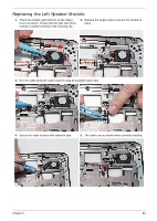
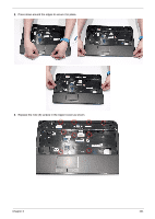
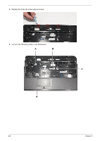
10. Turn the computer over and replace the eleven (11) screws as shown. Replacing the LCD Module 1. Align the screw holes on the LCD Module and Upper Cover and replace the LCD Module. 2. The left and right screw covers are shaped differently. Ensure that the correct cover is used. Left Screw Cover Right Screw Cover 3. Replace the left screw cover as shown. Ensure that the securing tab on the rear of the cover is seated correctly in the Upper Cover. 104 Chapter 3
-
 1
1 -
2
-
3
-
4
-
5
-
6
-
7
-
8
-
9
-
10
-
11
-
12
-
13
-
14
-
15
-
16
-
17
-
18
-
19
-
20
-
21
-
22
-
23
-
24
-
25
-
26
-
27
-
28
-
29
-
30
-
31
-
32
-
33
-
34
-
35
-
36
-
37
-
38
-
39
-
40
-
41
-
42
-
43
-
44
-
45
-
46
-
47
-
48
-
49
-
50
-
51
-
52
-
53
-
54
-
55
-
56
-
57
-
58
-
59
-
60
-
61
-
62
-
63
-
64
-
65
-
66
-
67
-
68
-
69
-
70
-
71
-
72
-
73
-
74
-
75
-
76
-
77
-
78
-
79
-
80
-
81
-
82
-
83
-
84
-
85
-
86
-
87
-
88
-
89
-
90
-
91
-
92
-
93
-
94
-
95
-
96
-
97
-
98
-
99
-
100
-
101
-
102
-
103
-
104
-
105
-
106
-
107
-
108
-
 109
109 -
 110
110 -
 111
111 -
 112
112 -
 113
113 -
 114
114 -
 115
115 -
 116
116 -
 117
117 -
 118
118 -
 119
119 -
120
-
121
-
122
-
123
-
124
-
125
-
126
-
127
-
128
-
129
-
130
-
131
-
132
-
133
-
134
-
135
-
136
-
137
-
138
-
139
-
140
-
141
-
142
-
143
-
144
-
145
-
146
-
147
-
148
-
149
-
150
-
151
-
152
-
153
-
154
-
155
-
156
-
157
-
158
-
159
-
160
-
161
-
162
-
163
-
164
-
165
-
166
-
167
-
168
-
169
-
170
-
171
-
172
-
173
-
174
-
175
-
176
-
177
-
178
-
179
-
180
-
181
-
182
-
183
-
184
-
185
-
186
-
187
-
188
-
189
-
190
-
191
-
192
-
193
-
194
-
195
-
196
-
197
-
198
 |
 |

104
Chapter 3
Replacing the LCD Module
10.
Turn the computer over and replace the eleven (11) screws as shown.
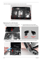
1.
Align the screw holes on the LCD Module and
Upper Cover and replace the LCD Module.
2.
The left and right screw covers are shaped
differently. Ensure that the correct cover is used.
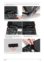
3.
Replace the left screw cover as shown. Ensure that the securing tab on the rear of the cover is seated
correctly in the Upper Cover.
Left Screw
Cover
Right Screw
Cover