3Com 4500G Getting Started Guide - Page 12
describes the rear panel of the Switch 4500G 24-Port unit. - 48 port
 |
UPC - 662705505534
View all 3Com 4500G manuals
Add to My Manuals
Save this manual to your list of manuals |
Page 12 highlights
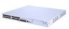
12 CHAPTER 1: INTRODUCING THE SWITCH 4500G FAMILY Figure 2 describes the rear panel of the Switch 4500G 24-Port unit. Figure 2 Switch 4500G 24-Port-rear panel (1) (2) (3) (4) (5) (1) AC power input (3) Grounding terminal (5) Extended slot 2 (4) Extended slot 1 Figure 3 describes the front panel of the Switch 4500G 48-Port unit. Figure 3 Switch 4500G 48-Port-front panel (1) 10/100/1000 BASE-T autosensing Ethernet port status LED (3) 7-segment digitron display (5) Mode LED (9) LED for extended slot 2 (2) Console port (4) Mode switching button (6) Power LED (8) LED for extended slot 1 (10) Gigabit SFP Combo port status LED
-
 1
1 -
2
-
3
-
4
-
5
-
6
-
 7
7 -
 8
8 -
 9
9 -
 10
10 -
 11
11 -
 12
12 -
 13
13 -
 14
14 -
 15
15 -
 16
16 -
 17
17 -
18
-
19
-
20
-
21
-
22
-
23
-
24
-
25
-
26
-
27
-
28
-
29
-
30
-
31
-
32
-
33
-
34
-
35
-
36
-
37
-
38
-
39
-
40
-
41
-
42
-
43
-
44
-
45
-
46
-
47
-
48
-
49
-
50
-
51
-
52
-
53
-
54
-
55
-
56
-
57
-
58
-
59
-
60
-
61
-
62
-
63
-
64
-
65
-
66
-
67
-
68
-
69
-
70
-
71
-
72
-
73
-
74
-
75
-
76
-
77
-
78
-
79
-
80
-
81
-
82
-
83
-
84
-
85
-
86
-
87
-
88
-
89
-
90
-
91
-
92
 |
 |

12
C
HAPTER
1: I
NTRODUCING
THE
S
WITCH
4500G F
AMILY
Figure 2 describes the rear panel of the Switch 4500G 24-Port unit.
Figure 2
Switch 4500G 24-Port—rear panel
Figure 3 describes the front panel of the Switch 4500G 48-Port unit.
Figure 3
Switch 4500G 48-Port—front panel
(1) AC power input
(3) Grounding terminal
(4) Extended slot 1
(5) Extended slot 2
(1) 10/100/1000 BASE-T autosensing
Ethernet port status LED
(2) Console port
(3) 7-segment digitron display
(4) Mode switching button
(5) Mode LED
(6) Power LED
(8) LED for extended slot 1
(9) LED for extended slot 2
(10) Gigabit SFP Combo port status LED
(1)
(3)
(4)
(5)
(1)
(3)
(4)
(5)