3M 2290 Operation Manual - Page 3
Operating Instructions, Resistive Characterization Of, Static Control Work, Surfaces
 |
View all 3M 2290 manuals
Add to My Manuals
Save this manual to your list of manuals |
Page 3 highlights
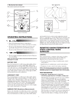
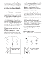
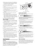
7. Mechanical Zero Adjust: This control is used to zero the pointer. TEST WEIGHTS 4 5 7 2 108 107 OHMS 109 106 1010 1011 1G 10G 100G 100M 10M 100M 10M 1M FAIL 100V 105 0 1M 100K 100K PASS 10K 0 0 BATTERY CONTINUITY TAUT BAND SUSPENSION BATTERY TEST CONTINUITY TEST OFF SURFACE TEST 10V 100V TEST READ MANUAL BEFORE USE Figure 3-1: Front Panel 3 1 6 108 107 OHMS 109 106 1010 1011 1G 10G 100G 100M 10M 100M 10M 1M FAIL 100V 105 0 1M 100K 100K PASS 10K 0 0 BATTERY CONTINUITY TAUT BAND SUSPENSION BATTERY TEST CONTINUITY TEST OFF SURFACE TEST 10V 100V TEST CALIBRATION PLATE READ MANUAL BEFORE USE Figure 4-1: Continuity Test OPERATING INSTRUCTIONS • Turn off the Instrument before connecting or disconnecting test leads, or before moving test weights. • Do not use this Instrument with any accessories not specifically designed to be used with this product. • Do not use this Instrument to measure live circuits. and attach the leads as shown in the appropriate sketch figures 5-1 through 5-5. Set the Main Selector Switch to the desired SURFACE TEST voltage. Place the test weight(s) on the surface to be tested and connect the test leads. Press TEST for 15 seconds and then read the resistance from the OHMS scale. After all readings have been completed, return the Main Selector Switch to the OFF position. RESISTIVE CHARACTERIZATION OF STATIC CONTROL WORK SURFACES • The test weights included in this kit are heavy. Exercise care in handling. NOTE: The following procedures should be followed each time the Model 701 is used. BATTERY TEST Place the Instrument on a table top or other stable surface. Set the main selector switch to BATTERY TEST. Press TEST and hold for 15 seconds. The pointer should come to rest in the green area of the BATTERY scale. If the pointer is in the red area to the left of 100V, replace the battery and retest. If the pointer is in the red area to the right of 100V, the Instrument may need recalibration. CONTINUITY TEST Place the Instrument on a table top or other stable surface and attach the leads as shown in Figure 4-1. Place the test weights on the calibration plate or other bare metal surface and plug in the test leads. Set the main selector switch to CONTINUITY TEST. Press TEST. The pointer should come to rest in the green section of the CONTINUITY scale. If not, the test leads may be defective or the weights may require maintenance or cleaning. SURFACE TEST (Resistance Measurement) Refer to the immediate two following sections to determine which measurement(s) should be used for your application. Place the Instrument on a table top or other stable surface GENERAL This section provides a summary of the types of surface measurements specified and described by ESD-S4.1. Measurements are performed for three reasons: 1. Periodic performance testing of installed static control work surfaces. 2. Qualification of installed static control work surfaces. 3. Evaluation of static control work surface materials. NOTE: The following paragraphs are offered as a condensed summary of the test methods and procedures outlined in the EOS/ESD standard. For complete details, refer to the standard. TEST DESCRIPTION 1. PERIODIC PERFORMANCE TESTING OF INSTALLED STATIC CONTROL SURFACES (Measurement of resistance from the top of an installed surface to ESD GROUND (RTS-ESDG) at ambient temperature and humidity): Note: ESD GROUND is the point at which the ground cord or other grounding conductor from the static control surface is connected to. The ground point may be an electrical ground, building ground, or other suitable ground. If you have questions concerning the correct ground, refer to EOS/ESD STANDARD S6.0 and/or contact a qualified electrician. This Resistance-to-Ground test is the most important test that can be done on a static control surface because it verifies that the surface is working correctly and will 2
-
 1
1 -
 2
2 -
 3
3 -
 4
4 -
 5
5 -
 6
6 -
 7
7 -
 8
8
 |
 |
