3M 2290 Operation Manual - Page 4
Qualification Of Installed Static, Control Surfaces, Evaluation Of Static Control, Materials
 |
View all 3M 2290 manuals
Add to My Manuals
Save this manual to your list of manuals |
Page 4 highlights
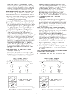
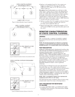
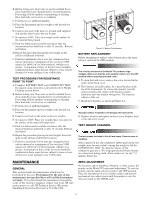
drain a static charge in a reasonable time. This test involves measurement of the total resistance from the static control surface through the conductor or ground cord to the ESD GROUND (ESDG), verifying that the entire static control system is functioning correctly. NOTE: ESD-S4. 1 suggests that a static control surface that measures in the range of 1x10⁶ ohms to 1x10¹⁰ ohms RTSESDG is acceptable. HOWEVER, 3M RECOMMENDS THAT A MORE CONSERVATIVE VALUE OF 1X10⁹ OHMS BE USED AS THE HIGHEST ACCEPTABLE RESISTANCE TO ESD GROUND. The following procedures should be followed when testing installed static control surfaces. A. Complete BATTERY TEST and CONTINUITY TEST. B. Set the Instrument on a table top or other stable surface and place a test weight at the desired test point as shown in Figure 5-1. Connect the test leads to the meter using the right angle banana plugs at the meter. Then connect one of the test leads to the test weight and the other to the ESD GROUND using one of the supplied clips. C. Test the static control surface using the 100 volts SURFACE TEST. Depress the TEST button for 15 seconds, allowing the pointer to stabilize; record the readings for each test point. If the reading is below 1x10⁶ ohms, check the static control surface for an alternate path to ground; correct and retest. If some or all the readings are above 1x10⁹ ohms, the static control surface may be dirty. Clean the surface using the manufacturer's recommended cleaning procedure followed by two clear water rinses and a rinse with 70% Isopropyl alcohol. Allow the surface to dry overnight and retest. If the resistance reading is "infinite," there is an interruption (open) in the ground connection; repair and retest. 2. QUALIFICATION OF INSTALLED STATIC CONTROL SURFACES [Measurement of resistance of the top surface to the groundable point of the static control surface (RTS-GP)]. GROUNDABLE POINT is the point at which the grounding conductor is connected to the static control surface; the GROUNDABLE POINT is most commonly a snap (mats), a bolt (laminate), or a strip of conductive foil tape (flooring). This QUALIFICATION measurement is similar to those described in the test description section and is used to verify the correct installation of the GROUNDABLE POINT by the manufacturer or by the user. While the test procedure is the same, the test setup is slightly different; see Figure 5-2. 3. EVALUATION OF STATIC CONTROL MATERIALS [Measurement of the resistance between two points on top of a static control surface (RTS-TS), and the resistance between a point on the surface and the groundable point (RTS-GP)]: Material measurements are done to determine the intrinsic electrical properties of static control work surface materials. NOTE: Values obtained by these tests may not reflect how a material will perform when installed as a static control surface. Material evaluations are typically done at two humidities (12% RH and 50% RH) to determine whether the electrical properties of the material are humiditydependent. If the low humidity test results are borderline or not within the expected ranges, caution should be exercised when using such materials in winter months or in dry conditions. To assure test accuracy, a minimum of six samples should be tested. The test procedure is as follows: A. Prepare a minimum of six samples of each material to be tested as shown in Figure 5-3. B. Clean samples to be tested with a 70% Isopropyl alcohol solution and condition at 73°F (23°C) and 50% RH for 48-72 hours. NOTE: Samples must be maintained at the appropriate humidity level throughout the test procedures. C. Complete BATTERY TEST and CONTINUITY TEST 2" 2" STATIC CONTROL SURFACE GROUNDABLE POINTS STATIC CONTROL SURFACE GROUNDABLE POINTS 108 107 OHMS 109 106 1010 1011 1G 10G 100G 100M 10M 100M 10M 1M FAIL 100V 105 0 1M 100K 100K PASS 10K 0 0 BATTERY CONTINUITY TAUT BAND SUSPENSION BATTERY TEST CONTINUITY TEST OFF SURFACE TEST 10V 100V TEST TO TEST WEIGHT AT TEST POINT A, B, C, D & E READ MANUAL BEFORE USE Figure 5-1: Periodic Performance Tests of Installed Surfaces 108 107 OHMS 109 106 1010 1011 1G 10G 100G 100M 10M 100M 10M 1M FAIL 100V 105 0 1M 100K 100K PASS 10K 0 0 BATTERY CONTINUITY TAUT BAND SUSPENSION TO TEST WEIGHT AT TEST POINT A, B, C, D & E BATTERY TEST CONTINUITY TEST OFF SURFACE TEST 10V 100V TEST READ MANUAL BEFORE USE Figure 5-2: Qualification Tests of Installed Surfaces 3
-
 1
1 -
 2
2 -
 3
3 -
 4
4 -
 5
5 -
 6
6 -
 7
7 -
 8
8
 |
 |
