3M 2290 Operation Manual - Page 6
Maintenance
 |
View all 3M 2290 manuals
Add to My Manuals
Save this manual to your list of manuals |
Page 6 highlights
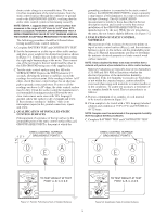
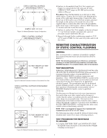
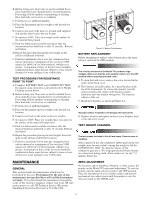
B. Before testing new floor mats or newly installed floors, clean mats/floors per manufacturer's recommendations. For testing of floor finishes or monitoring of existing floor materials, test in an as-is condition. C. Perform tests at ambient humidity. D. Place the Instrument and test weight at the desired test location. E. Connect one lead of the meter to ground with supplied clip and the other lead to the test weight. F. Set meter to 100V. Place test weight on the surface of the material being tested. G. Push test button and record the resistance after the measurement has stabilized or after 15 seconds. Release test button. H. Repeat the procedure placing the test weight on the surface at different locations. I. Perform a minimum of five tests per contiguous floor surface material or a minimum of five tests per 5,000 square feet (464,5 m2) of floor material, whichever is greater. A minimum of three of the five tests should be conducted in those areas that are subject to wear or have chemical or water spillage or are visibly dirty. TEST PROCEDURE FOR RESISTANCE POINT TO POINT A. Complete BATTERY TEST and CONTINUITY TEST. If required clean electrodes as described in Test Weight Cleaning section below. B. Before testing new floor mats or newly installed floors, clean mats/floors per manufacturer's recommendations. For testing of floor finishes or monitoring of existing floor materials, test in an as-is condition. C. Perform tests at ambient humidity. D. Place the Instrument and test weight at the desired test location. E. Connect test leads of the meter to the test weights. F. Set meter to 100V. Place test weights three feet apart on the surface of the material being tested. G. Push test button and record the resistance after the measurement has stabilized or after 15 seconds. Release test button. H. Repeat the procedure placing the test weights three feet apart on the surface at different locations. I. Perform a minimum of five tests per contiguous floor surface material or a minimum of five tests per 5,000 square feet (464,5 m2) of floor material, whichever is greater. A minimum of three of the five tests should be conducted in those areas that are subject to wear or have chemical or water spillage or are visibly dirty. MAINTENANCE GENERAL This section details the maintenance which may be performed by the user. Performance by the user of any maintenance not specified here will void the Instrument warranty. If it is determined that maintenance beyond the scope of this section is required, contact your local 3M sales representative or call 3M Technical Service (Electronic Handling & Protection Division) at 512-984-3200. Figure 6-1: Battery Replacement BATTERY REPLACEMENT Before attempting to replace either battery, place the main selector switch in the OFF position. The circuitry enclosed in the Model 701 produces high voltages. Make sure that the main selector switch is in the OFF position before removing the back cover. A. To open the back cover, remove the screw located in the center of the back cover. B. The batteries are held in place by a metal bracket at the top of the Instrument. To release this bracket, turn the screw located in the center of the bracket counter clockwise until the bracket swings free. The batteries will now slide out. C. Install new batteries as shown in Figure 6-1. Improper battery installation will damage this Instrument. D. Replace bracket and tighten bracket screw. Replace back cover and cover screw. TEST WEIGHT CLEANING The test probes included in this kit are heavy. Exercise care in handling. After a period of use, the conductive rubber pads on the test weights may become soiled, causing the weight to fail the CONTINUITY TEST. To clean the surface of the conductive pad, use a 70% Isopropyl alcohol/water mixture on a clean low-linting cloth. Allow surface to "air dry" 15 minutes before use. ZERO ADJUSTMENT On occasion, due to handling, vibration, or other causes, the pointer on the Model 701 may need adjustment. To zero the pointer, turn the main selector switch to the OFF position. Place the Instrument on a level stable surface and turn the mechanical zero adjust screw until the pointer is over the left-most mark on the OHMS scale. 5
-
 1
1 -
 2
2 -
 3
3 -
 4
4 -
 5
5 -
 6
6 -
 7
7 -
 8
8
 |
 |
