3M 2290 Operation Manual - Page 5
Resistive Characterization, Of Static Control Flooring
 |
View all 3M 2290 manuals
Add to My Manuals
Save this manual to your list of manuals |
Page 5 highlights
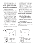
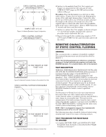
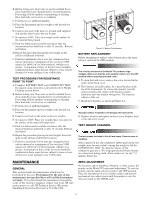
2" 2" STATIC CONTROL SURFACE GROUNDABLE POINTS 10" 10" SAMPLE SIZE: 10" X 24" Figure 5-3: Material Evaluation Sample Configuration STATIC CONTROL SURFACE GROUNDABLE POINTS 108 107 OHMS 109 106 1010 1011 1G 10G 100G 100M 10M 100M 10M 1M FAIL 100V 105 0 1M 100K 100K PASS 10K 0 0 BATTERY CONTINUITY TAUT BAND SUSPENSION TO TEST WEIGHT AT TEST POINT A & B BATTERY TEST CONTINUITY TEST OFF SURFACE TEST 10V 100V TEST READ MANUAL BEFORE USE Figure 5-4: Material Evaluation Surface to Groundable Point Test STATIC CONTROL SURFACE GROUNDABLE POINTS 108 107 OHMS 109 106 1010 1011 1G 10G 100G 100M 10M 100M 10M 1M FAIL 100V 105 0 1M 100K 100K PASS 10K 0 0 BATTERY CONTINUITY TAUT BAND SUSPENSION TO TEST WEIGHT AT TEST POINT A & B BATTERY TEST CONTINUITY TEST OFF SURFACE TEST 10V 100V TEST READ MANUAL BEFORE USE Figure 5-5: Material Evaluation Surface to Surface Test D. Surface-to-Groundable Point Test: Test samples per Figure 5-4, using both the 100 volts and 10 volts SURFACE TEST ranges at 50% RH and record the values as (RTS-GP). Procedure: Place the Instrument on a table top or other stable surface. Connect the test leads to the Instrument by means of the right angle banana plugs. Connect the other end of one of the leads to one of the test weights and place the weight on the surface to be tested. Use one of the supplied clips to connect the other lead to the groundable point on the static control surface. Depress TEST button for 15 seconds and then record the reading. E. Surface-to-surface Test: Test samples as shown in Figure 5-5; use both test weights and repeat the same test procedure used to determine (RTS-GP). F. Repeat A through E after conditioning samples at 73°F (23°C) and 12% RH. Use the same test points and record the values. RESISTIVE CHARACTERIZATION OF STATIC CONTROL FLOORING GENERAL This section provides a summary of installed or applied floor material measurements specified and described by ESD-S7.1. NOTE: The following paragraphs are offered as a condensed summary of the test methods and procedures outlined in the EOS/ESD standard. For complete details, refer to the standard. TEST DESCRIPTION PERIODIC PERFORMANCE TESTING OF INSTALLED OR APPLIED FLOORING MATERIALS(Measurement of resistance from the surface of an installed floor to GROUNDABLE POINT at ambient temperature and humidity): Note: GROUNDABLE POINT is a point on the floor material that is intended to accommodate an electrical connection from the floor material to an appropriate electrical ground. The ground point may be an electrical ground, building ground, or other suitable ground. If you have questions concerning the correct ground, refer to EOS/ESD Standard 6.0 and/or contact a qualified electrician. The Resistance-to-Ground test is the most important test that can be done on a static control surface because it verifies that the surface is working correctly and will drain a static charge in a reasonable time. This test involves measurement of the total resistance from the static control surface through the conductor or ground cord to the ESD to the ESD GROUND (ESDG), verifying that the entire static control system is functioning correctly. NOTE: ESD 7.1 is designed to measure floor materials with resistances of 2.5 x 10⁴ to 1.0 x 10¹¹ ohms. The following procedures should be followed when testing installed static control floor mats or flooring surfaces. TEST PROCEDURE FOR RESISTANCE TO GROUND A. Complete BATTERY TEST and CONTINUITY TEST. If required clean, electrodes as described in Test Weight Cleaning section page 5. 4
-
 1
1 -
 2
2 -
 3
3 -
 4
4 -
 5
5 -
 6
6 -
 7
7 -
 8
8
 |
 |
