3Ware 9690SA-4I4E-SGL Installation Guide - Page 23
controller, making sure to, and align the BBU control module and
 |
UPC - 693494500448
View all 3Ware 9690SA-4I4E-SGL manuals
Add to My Manuals
Save this manual to your list of manuals |
Page 23 highlights
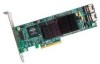
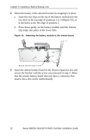
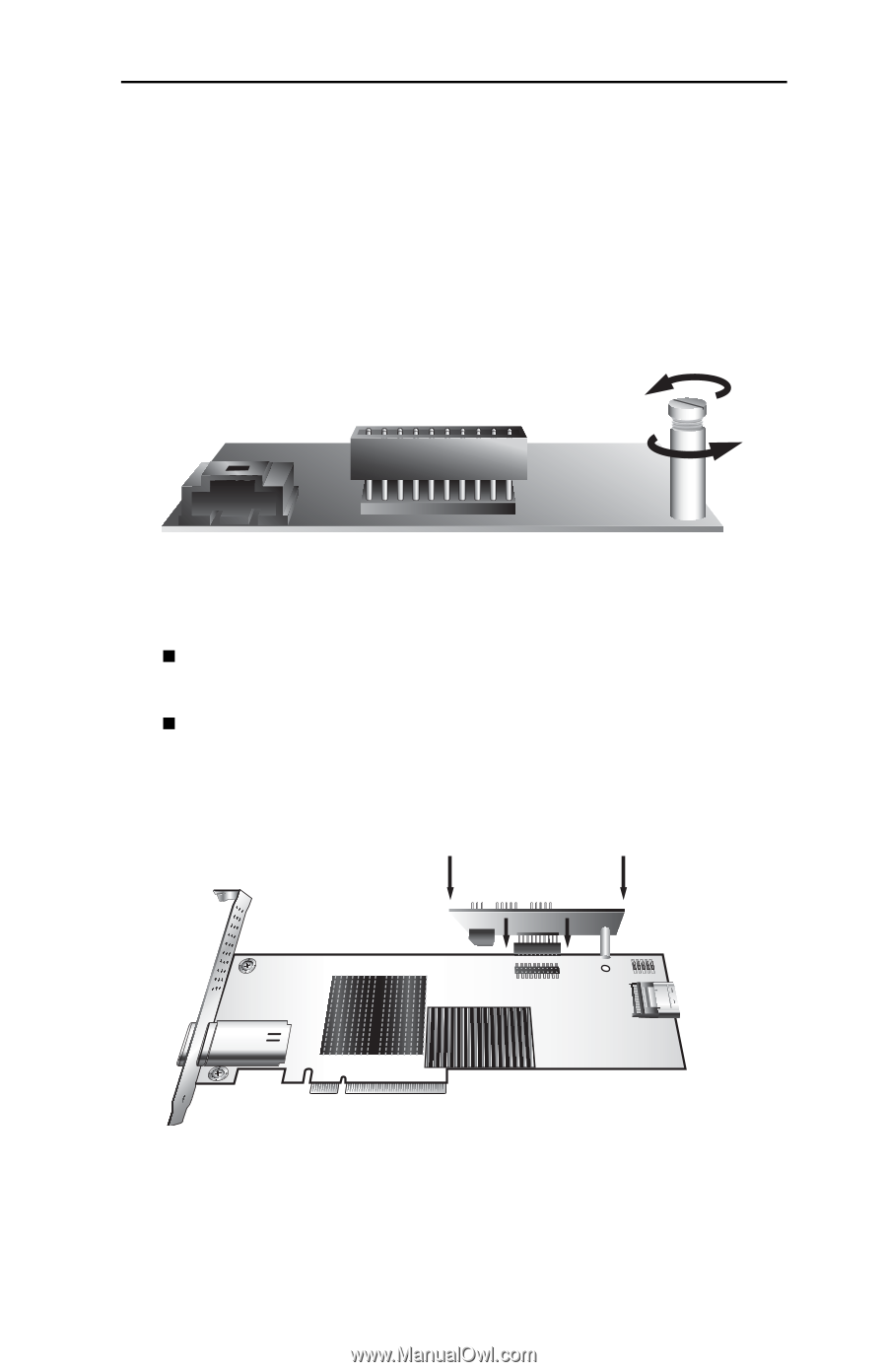
Installing the Control Module To install the control module Note: The following illustrations show the 9690SA-4I4E. If you have a 9690SA-8E the location of the control module post hole will be different. 1 Remove the screw head from the plastic post on the BBU control module and set it aside (you will reattach it soon.) Figure 11. Removing the head from the plastic post 2 Position the BBU control module above the controller (Figure 12) and align the BBU control module and the controller, making sure to: „ Mate the connector on the BBU control module with the receptacle on the controller. „ Match the plastic post on the BBU with the hole on the controller. Figure 12. BBU control module ready to connect to the controller www.3ware.com 19
-
 1
1 -
2
-
3
-
4
-
5
-
6
-
7
-
8
-
9
-
10
-
11
-
12
-
13
-
14
-
15
-
16
-
17
-
 18
18 -
 19
19 -
 20
20 -
 21
21 -
 22
22 -
 23
23 -
 24
24 -
 25
25 -
 26
26 -
 27
27 -
 28
28 -
29
-
30
-
31
 |
 |
Installing the Control Module
www.3ware.com
19
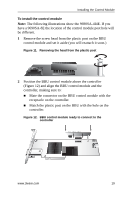
To install the control module
Note:
The following illustrations show the 9690SA-4I4E. If you
have a 9690SA-8E the location of the control module post hole will
be different.
1
Remove the screw head from the plastic post on the BBU
control module and set it aside (you will reattach it soon.)
Figure 11.
Removing the head from the plastic post
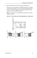
2
Position the BBU control module above the controller
(Figure 12) and align the BBU control module and the
controller, making sure to:
Mate the connector on the BBU control module with the
receptacle on the controller.
Match the plastic post on the BBU with the hole on the
controller.
Figure 12.
BBU control module ready to connect to the
controller