AMD AX2000DMT3C User Guide - Page 4

Signal and Power-Up Requirements .43, Mechanical Data, Pin Descriptions, Table of Contents - athlon

Page 4 highlights

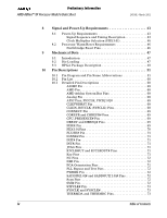
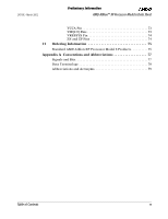
Preliminary Information AMD Athlon™ XP Processor Model 6 Data Sheet 24309E-March 2002 8 Signal and Power-Up Requirements 43 8.1 Power-Up Requirements 43 Signal Sequence and Timing Description 43 Clock Multiplier Selection (FID[3:0 46 8.2 Processor Warm Reset Requirements 46 Northbridge Reset Pins 46 9 Mechanical Data 47 9.1 Introduction 47 9.2 Die Loading 47 9.3 OPGA Package Description 48 10 Pin Descriptions 51 10.1 Pin Diagram and Pin Name Abbreviations 51 10.2 Pin List 60 10.3 Detailed Pin Descriptions 68 A20M# Pin 68 AMD Pin 68 AMD Athlon System Bus Pins 68 Analog Pin 68 APIC Pins, PICCLK, PICD[1:0 68 CLKFWDRST Pin 68 CLKIN, RSTCLK (SYSCLK) Pins 68 CONNECT Pin 69 COREFB and COREFB# Pins 69 CPU_PRESENCE# Pin 69 DBRDY and DBREQ# Pins 69 FERR Pin 69 FID[3:0] Pins 70 FLUSH# Pin 71 IGNNE# Pin 71 INIT# Pin 71 INTR Pin 71 JTAG Pins 71 K7CLKOUT and K7CLKOUT# Pins 71 Key Pins 71 NC Pins 72 NMI Pin 72 PGA Orientation Pins 72 PLL Bypass and Test Pins 72 PWROK Pin 72 SADDIN[1:0]# and SADDOUT[1:0]# Pins 72 Scan Pins 72 SMI# Pin 72 STPCLK# Pin 73 SYSCLK and SYSCLK 73 THERMDA and THERMDC Pins 73 iv Table of Contents

  • 1
  • 2
  • 3
  • 4
  • 5
  • 6
  • 7
  • 8
  • 9
  • 10
  • 11
  • 12
  • 13
  • 14
  • 15
  • 16
  • 17
  • 18
  • 19
  • 20
  • 21
  • 22
  • 23
  • 24
  • 25
  • 26
  • 27
  • 28
  • 29
  • 30
  • 31
  • 32
  • 33
  • 34
  • 35
  • 36
  • 37
  • 38
  • 39
  • 40
  • 41
  • 42
  • 43
  • 44
  • 45
  • 46
  • 47
  • 48
  • 49
  • 50
  • 51
  • 52
  • 53
  • 54
  • 55
  • 56
  • 57
  • 58
  • 59
  • 60
  • 61
  • 62
  • 63
  • 64
  • 65
  • 66
  • 67
  • 68
  • 69
  • 70
  • 71
  • 72
  • 73
  • 74
  • 75
  • 76
  • 77
  • 78
  • 79
  • 80
  • 81
  • 82
  • 83
  • 84
  • 85
  • 86
  • 87
  • 88
  • 89
  • 90
  • 91
  • 92
  • 93
  • 94

iv
Table of Contents
AMD Athlon™ XP Processor Model 6 Data Sheet
24309E—March 2002
Preliminary Information
8
Signal and Power-Up Requirements . . . . . . . . . . . . . . . . . . . . 43
8.1
Power-Up Requirements . . . . . . . . . . . . . . . . . . . . . . . . . . . . . 43
Signal Sequence and Timing Description . . . . . . . . . . . . . 43
Clock Multiplier Selection (FID[3:0]) . . . . . . . . . . . . . . . . 46
8.2
Processor Warm Reset Requirements
. . . . . . . . . . . . . . . . . . 46
Northbridge Reset Pins. . . . . . . . . . . . . . . . . . . . . . . . . . . . 46
9
Mechanical Data
. . . . . . . . . . . . . . . . . . . . . . . . . . . . . . . . . . . . 47
9.1
Introduction
. . . . . . . . . . . . . . . . . . . . . . . . . . . . . . . . . . . . . . . 47
9.2
Die Loading . . . . . . . . . . . . . . . . . . . . . . . . . . . . . . . . . . . . . . . . 47
9.3
OPGA Package Description . . . . . . . . . . . . . . . . . . . . . . . . . . . 48
10
Pin Descriptions
. . . . . . . . . . . . . . . . . . . . . . . . . . . . . . . . . . . . 51
10.1
Pin Diagram and Pin Name Abbreviations
. . . . . . . . . . . . . . 51
10.2
Pin List
. . . . . . . . . . . . . . . . . . . . . . . . . . . . . . . . . . . . . . . . . . . 60
10.3
Detailed Pin Descriptions
. . . . . . . . . . . . . . . . . . . . . . . . . . . . 68
A20M# Pin . . . . . . . . . . . . . . . . . . . . . . . . . . . . . . . . . . . . . . 68
AMD Pin . . . . . . . . . . . . . . . . . . . . . . . . . . . . . . . . . . . . . . . . 68
AMD Athlon System Bus Pins . . . . . . . . . . . . . . . . . . . . . . 68
Analog Pin . . . . . . . . . . . . . . . . . . . . . . . . . . . . . . . . . . . . . . 68
APIC Pins, PICCLK, PICD[1:0]# . . . . . . . . . . . . . . . . . . . . 68
CLKFWDRST Pin . . . . . . . . . . . . . . . . . . . . . . . . . . . . . . . . 68
CLKIN, RSTCLK (SYSCLK) Pins. . . . . . . . . . . . . . . . . . . . 68
CONNECT Pin . . . . . . . . . . . . . . . . . . . . . . . . . . . . . . . . . . . 69
COREFB and COREFB# Pins . . . . . . . . . . . . . . . . . . . . . . . 69
CPU_PRESENCE# Pin . . . . . . . . . . . . . . . . . . . . . . . . . . . . 69
DBRDY and DBREQ# Pins . . . . . . . . . . . . . . . . . . . . . . . . . 69
FERR Pin . . . . . . . . . . . . . . . . . . . . . . . . . . . . . . . . . . . . . . . 69
FID[3:0] Pins . . . . . . . . . . . . . . . . . . . . . . . . . . . . . . . . . . . . 70
FLUSH# Pin . . . . . . . . . . . . . . . . . . . . . . . . . . . . . . . . . . . . . 71
IGNNE# Pin . . . . . . . . . . . . . . . . . . . . . . . . . . . . . . . . . . . . . 71
INIT# Pin . . . . . . . . . . . . . . . . . . . . . . . . . . . . . . . . . . . . . . . 71
INTR Pin. . . . . . . . . . . . . . . . . . . . . . . . . . . . . . . . . . . . . . . . 71
JTAG Pins . . . . . . . . . . . . . . . . . . . . . . . . . . . . . . . . . . . . . . . 71
K7CLKOUT and K7CLKOUT# Pins. . . . . . . . . . . . . . . . . . 71
Key Pins . . . . . . . . . . . . . . . . . . . . . . . . . . . . . . . . . . . . . . . . 71
NC Pins . . . . . . . . . . . . . . . . . . . . . . . . . . . . . . . . . . . . . . . . . 72
NMI Pin. . . . . . . . . . . . . . . . . . . . . . . . . . . . . . . . . . . . . . . . . 72
PGA Orientation Pins . . . . . . . . . . . . . . . . . . . . . . . . . . . . . 72
PLL Bypass and Test Pins . . . . . . . . . . . . . . . . . . . . . . . . . . 72
PWROK Pin . . . . . . . . . . . . . . . . . . . . . . . . . . . . . . . . . . . . . 72
SADDIN[1:0]# and SADDOUT[1:0]# Pins . . . . . . . . . . . . . 72
Scan Pins . . . . . . . . . . . . . . . . . . . . . . . . . . . . . . . . . . . . . . . 72
SMI# Pin . . . . . . . . . . . . . . . . . . . . . . . . . . . . . . . . . . . . . . . . 72
STPCLK# Pin . . . . . . . . . . . . . . . . . . . . . . . . . . . . . . . . . . . . 73
SYSCLK and SYSCLK#. . . . . . . . . . . . . . . . . . . . . . . . . . . . 73
THERMDA and THERMDC Pins. . . . . . . . . . . . . . . . . . . . 73