ASRock ALiveSATA2-GLAN User Manual - Page 19
motherboard. Each USB 2.0
 |
View all ASRock ALiveSATA2-GLAN manuals
Add to My Manuals
Save this manual to your list of manuals |
Page 19 highlights
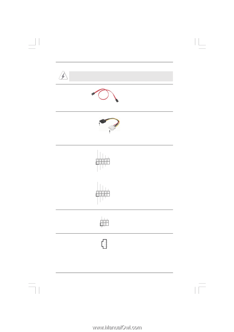
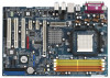
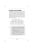
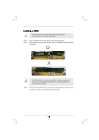
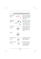
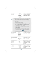
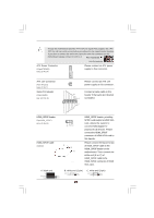
It is recommended to plug SATAII HDD to SATAII connector (SATAII_1 or SATAII_2) and connect SATA HDD to SATA connector (SATA1 or SATA2). Serial ATA (SATA) Data Cable (Optional) Either end of the SATA data cable can be connected to the SATA / SATAII hard disk or the SATA / SATAII connector on the motherboard. Serial ATA (SATA) Power Cable (Optional) connect to the SATA HDD power connector connect to the power supply Please connect the black end of SATA power cable to the power connector on the drive. Then connect the white end of SATA power cable to the power connector of the power supply. USB 2.0 Headers (9-pin USB6_7) (see p.10 No. 10) USB_PWR P-7 P+7 GND DUMMY 1 GND P+6 P-6 USB_PWR Besides four default USB 2.0 ports on the I/O panel, there are two USB 2.0 headers on this motherboard. Each USB 2.0 header can support two USB 2.0 ports. (9-pin USB4_5) (see p.10 No. 11) USB_PWR P-4 P+4 GND DUMMY 1 GND P+5 P-5 USB_PWR Infrared Module Header (5-pin IR1) (see p.10, No. 30) Internal Audio Connector (4-pin CD1) (CD1: see p.10, No. 33) IRTX +5VSB DUMMY 1 GND IRRX CD-L GND GND CD-R CD1 This header supports an optional wireless transmitting and receiving infrared module. This connector allows you to receive stereo audio input from sound sources such as a CD-ROM, DVD-ROM, TV tuner card, or MPEG card. 19
-
 1
1 -
2
-
3
-
4
-
5
-
6
-
7
-
8
-
9
-
10
-
11
-
12
-
13
-
 14
14 -
 15
15 -
 16
16 -
 17
17 -
 18
18 -
 19
19 -
 20
20 -
 21
21 -
 22
22 -
 23
23 -
 24
24 -
25
-
26
-
27
-
28
-
29
-
30
-
31
-
32
-
33
-
34
-
35
-
36
-
37
-
38
-
39
-
40
-
41
-
42
-
43
-
44
-
45
-
46
-
47
 |
 |