ASRock FM2A85X Extreme6 User Manual - Page 15
I/O Panel - rear audio
 |
View all ASRock FM2A85X Extreme6 manuals
Add to My Manuals
Save this manual to your list of manuals |
Page 15 highlights
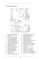
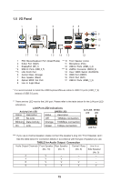
1.5 I/O Panel 1 2 3 45 69 7 10 8 11 17 16 15 14 13 12 1 PS/2 Mouse/Keyboard Port (Green/Purple) *** 10 Front Speaker (Lime) 2 D-Sub Port (VGA1) 11 Microphone (Pink) 3 DisplayPort (DP_1) 12 USB 3.0 Ports (USB3_3_4) * 4 USB 2.0 Ports (USB_6_7) **** 13 eSATA3 Connector (SATA3_6) ** 5 LAN RJ-45 Port 14 Clear CMOS Switch (CLRCBTN) 6 Central / Bass (Orange) 15 HDMI Port (HDMI1) 7 Rear Speaker (Black) 16 DVI-D Port (DVI1) 8 Optical SPDIF Out Port 17 USB 3.0 Ports (USB3_1_2) 9 Line In (Light Blue) * It is recommended to install the USB Keyboard/Mouse cable to USB 2.0 ports (USB_7_9) instead of USB 3.0 ports. ** There are two LED next to the LAN port. Please refer to the table below for the LAN port LED indications. LAN Port LED Indications Activity/Link LED SPEED LED Status Description Status Description ACT/LINK SPEED LED LED Off No Link Off 10Mbps connection Blinking Data Activity Orange 100Mbps connection On Link Green 1Gbps connection LAN Port *** If you use 2-channel speaker, please connect the speaker's plug into "Front Speaker Jack". See the table below for connection details in accordance with the type of speaker you use. TABLE for Audio Output Connection Audio Output Channels Front Speaker Rear Speaker Central / Bass Line In or (No. 10) (No. 7) (No. 6) Side Speaker (No. 9) 2 V -- -- -- 4 V V -- -- 6 V V V -- 8 V V V V 15
-
 1
1 -
2
-
3
-
4
-
5
-
6
-
7
-
8
-
9
-
 10
10 -
 11
11 -
 12
12 -
 13
13 -
 14
14 -
 15
15 -
 16
16 -
 17
17 -
 18
18 -
 19
19 -
 20
20 -
21
-
22
-
23
-
24
-
25
-
26
-
27
-
28
-
29
-
30
-
31
-
32
-
33
-
34
-
35
-
36
-
37
-
38
-
39
-
40
-
41
-
42
-
43
-
44
-
45
-
46
-
47
-
48
-
49
-
50
-
51
-
52
-
53
-
54
-
55
-
56
-
57
-
58
-
59
-
60
-
61
-
62
-
63
-
64
-
65
-
66
-
67
-
68
-
69
-
70
-
71
-
72
-
73
-
74
-
75
-
76
-
77
 |
 |
